Information Technology Reference
In-Depth Information
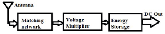
Fig. 1.
Block Diagram of Energy harvesting circuit
the GSM bandwidth (890-915MHz and 935-960MHz), these signals carry maxi-
mum power but only a small amount can be harvested due to heat dissipation
or absorption by other materials, so multiple stages of voltage multiplier are
required to reach at appropriate level that can charge the wireless devices. Fig.1
shows the block diagram of a typical RF energy harvester circuit. The matching
network composed of inductive and capacitive elements, ensures the maximum
power delivery from antenna to voltage multiplier. The received RF power is
converted into dc power by the voltage multiplier. The energy storage ensures
smooth power delivery to the load, and as a reservoir for durations when external
energy is unavailable[3].
Smaller number of the multiplier stages will make certain immediate charging
of the capacitor, so the result is a small amount of the voltage generated that
may be inadequate to operate sensor mote besides increasing the number of
voltage multiplier stages, a slight change in the matching circuit parameter alters
drastically the frequency range in which the eciency of the energy conversion
is maximum often by several MHz[3]. Hence, to design RF energy harvester
involves a very essential part to choose the parameter of the circuit.
2 Design Methodology of Energy Harvesting Circuit
The incident RF energy need to be convertedintousabledcpowerrequirean
antenna with high directivity to receive more incident RF energy because the
gain of the antenna is directly proportional to its directivity[11], a matching
circuit to match the load impedance with the antenna impedance and rectifier
circuit to develop the required voltage at the output, for this many approaches
have been reported in the literature[4],[5],[6] and [7].
But according to Friis transmission equation[8]:
P
r
=
P
t
G
t
G
r
ʻ
2
(4
ˀR
)
2
(1)
where
P
r
= Received power
P
t
= Transmitted power
G
t
= Gain of the transmitted antenna
G
r
= Gain of the receiver antenna
R
= Distance between the transmitter and receiver antennas
ʻ
= wavelength of the transmitted signal.