Graphics Reference
In-Depth Information
Application coordinate system
Circle of 20
App
l
lic
ti
ation coo
di
rdi
t
nate s
t
ystem
Circle of 20
3
20 units, centered at origin
20 units, centered at origin
x
3
Scale transform
by 4.8 on both axes
y
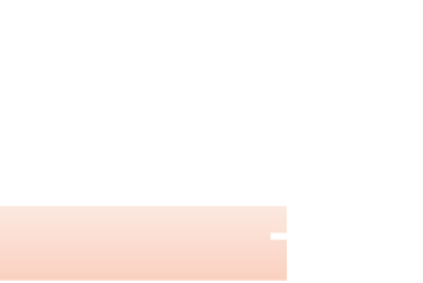
Figure 2.13: Schematic view of our application now enhanced with a scale transform.
Here is the revised XAML (V.03 in the lab);
its effect
is depicted in
Figure 2.14.
1
2
3
4
5
6
7
8
9
10
11
12
<Canvas ... >
<!- THE SCENE ->
<Ellipse ... />
<!- THE DISPLAY TRANSFORM ->
<Canvas.RenderTransform>
<TransformGroup>
<ScaleTransform ScaleX=
"4.8"
ScaleY=
"4.8"
... />
<TranslateTransform X="48" Y="48" />
</TransformGroup>
</Canvas.RenderTransform>
</Canvas>
NOTE:
Animated versions of all of the application schematic views in this
chapter are provided as part of the online material.
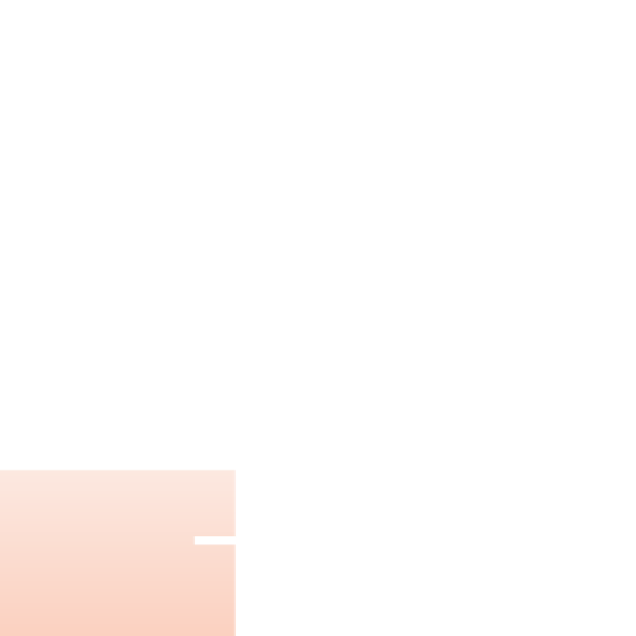
To review: We have used a sequence of transforms, attached to the canvas,
to perform what we call a display transformation to execute the geometric adap-
tations necessary to make our scene have the desired spatial appearance on the
display device. The display transformation maps our application coordinate sys-
tem to WPF's canvas coordinate system; we indicate this goal state by highlighting
the coordinate system's representation with a drop shadow.
Application coordinate system
Circle of 20 3 20 units, centered at origin
Applicati
on coo
rdinat
e s
yst
em
Circle of 20 3 20 units, centered at origin
x
Scale transform
by 4.8 on both axes
Scale
tra
nsf
orm
by 4.8 on both axe
s
Translate transform
x
:
y
1
48
y
:
1
48
WPF canvas coordinate system
Figure 2.14: Schematic view of our application now enhanced with a two-step display-
transform sequence (scale and translate).