Graphics Reference
In-Depth Information
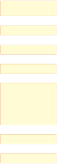
Simulate
(includes AI & Physics)
Dynamic 3D geometry
Pose
Static 3D geometry
Texture
Forward trace
Cull
Reduced 3D geometry
Backward trace
Transform
For each pixel
CSG
Surface intersection
Shade
Recursive tracing
2D Radiance image
Post-process
Displayable 2D image
Figure 33.2: The steps involved in a basic ray tracer.
Immediate-mode packages like GL in its early forms provided ways to represent,
in the sequence of instructions issued to the package (typically by function calls),
something about the
structure
of the objects to be drawn. If an object was modeled
with a hierarchy of transformations, then the sequence of GL calls would reflect
this, pushing and popping matrix transformations from a stack that represented a
current transformation to be applied to all subsequent vertices. These transformed
vertices, together with vertex-index triples representing triangles, formed the core
of what was to be rendered. The rendering process followed a fairly straightfor-
ward path, which can be coarsely summarized by saying that a collection of tri-
angles with per-vertex and per-triangle attributes were described to the system,
often with various transformations applied to the vertices. The resultant trian-
gles were then transformed to the standard perspective view volume, and clipped
against the near clipping plane. They were then transformed to the standard par-
allel view volume, and clipped against the remaining clipping planes. The resul-
tant triangles were then rasterized, the rasterized pixels were shaded (i.e., some
computation was done to determine their color, a computation that often involved
texture lookup), and the triangles were placed into a Z-buffer, with only the front-
most remaining in the final image. Sometimes the resultant image was combined
with some preexisting image via a compositing operation so that multiple objects