Graphics Reference
In-Depth Information
ray to see some other point is typically the result of some floating-point compu-
tation going wrong: A number you expected to be slightly greater than zero was
in fact slightly less. The dependence of this error on the point locations is likely
to be tied to the floating-point representation, and to generate random results like
speckle. But sometimes there's a strong enough dependence on a single parameter
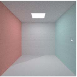
that there's regularity in the results. Figure 32.19 shows how the floor of the Cor-
nell box is irregularly illuminated (a triangle in the back-right corner is too dark)
when we fail to bump just the light-point position.
Suppose that your photon mapper shows nice, smooth gradations of reflected
light in the Cornell box, but there's no color bleeding: The left side of the floor
isn't slightly red and the right side isn't slightly blue. Think for a moment about
what might be wrong, and then read on.
One thing to ask is, “Are the photons correct?” You can plot each photon as
a point in your scene to verify that they're well scattered, and you can even plot
each one as a small arrow whose base is at the photon location, and which points
toward the source of the light. If all the photons point toward the area light, there's
a problem: You're not getting any scattered photons in your photon map. (You're
also storing first-hit photons, which may be intentional, but if you're computing
direct illumination in a separate step, as we did, it's a mistake: You'll end up
double-counting the direct illumination!) Interpolating values from the photons
you have will tend to give smoothly varying light, however. But you won't get
color bleeding. Let's assume, though, that the photons are well scattered, only
store indirect light, and seem to get their indirect light from many different places.
A photon on the floor near the red wall probably got there by having light hit
the red wall and reflect to the floor. The problem
has
to be in the reflection process,
that is, the multiplication by the BRDF and a cosine. Since the magnitude looks
right, the absorption/reflection part of the code must be right. But the spectral
distribution of the outgoing photon's power is evidently wrong. What color
should
that photon be? Fairly red! By drawing your photons as small disks colored by the
color of the arriving light, you can rapidly tell whether they're correct or not.
When you discover that all your photons are white, you've found the problem:
During multiple bounces, the photon power wasn't being multiplied by the color
of the surface from which it was reflecting.
As another example, suppose that you've decided to improve your photon
mapper with a final-gather step. You wisely keep the no-gather part of the pro-
gram, and include a checkbox in the user interface to determine whether gather-
ing is used or not. When you switch from no-gather to gather, the picture looks
almost the same, but a bit dimmer. If you turn off direct light, it's evidently
alot
dimmer. In fact, by inspecting and comparing individual pixels, you find that the
pixel values are all dropping by a factor of about three. Once again, think briefly
about where the error must be, and then read on.
When you encounter a number near 3 in a renderer, surprisingly often it's
really
Figure 32.19: A diagonal stripe
on the floor from failed visibility
testing.
9.87.) In this case, when this
problem arose for one author it was because he used cosine-weighted samples
for his gathering, multiplied each by the appropriate
f
s
(
2
≈
π
. (Similarly, a factor of 10 is often
π
v
i
,
v
o
)
factor, but not
the cosine (
n
), because the cosine was included in the sampling weights,
and then averaged the results. The difficulty was the failure to divide by
v
i
·
(the
result of doing a cosine-weighted sampling of the constant function 1 on the upper
hemisphere).
Suppose that in path-tracing our second model—the one with the glass
sphere—we'd seen the reflection of the adjacent solid sphere and of the area light
π