Graphics Reference
In-Depth Information
For the same reason, when we use a measured BRDF in rendering it's important
that an imager pixel correspond to a surface region whose area is as large or larger
than the area used in gathering the BRDF in the first place.
Inline Exercise 27.8:
The wavelength of visible light is between one-half
and one micron; it's convenient to treat it as about one micron for back-of-
the-envelope estimation. To prevent diffraction effects from being significant,
microfacets should be at least a couple of wavelengths (say, five) in their min-
imum dimension. In a surface that's fairly flat (most microfacets have slope
less than 45
◦
), we can imagine each microfacet is a small disk or square, so its
projected length, in any direction, is at least .71
cos(
45
◦
)
times its minimum
≈
dimension.
(a) Approximately how many such microfacets can fit into a 1mm-diameter
disk?
(b) If you had that many small mirrorlike facets in such a disk and illuminated
them with a laser pointer whose beam covered just that disk, what would the
pattern of reflected light look like? Get a laser pointer, a piece of polished
metal, and a piece of white paper to “catch” the outgoing light and see whether
the reflected light follows the predicted pattern.
v
i
=
n
), the scattered
light goes in many directions: If the grooves are all shallow, most of it reflects
back in the normal direction; if they're deep, there's much more scattering in
off-normal directions. But for illumination arriving in an off-normal direction,
multiple phenomena combine to generate the scattering pattern.
For illumination arriving along the normal direction (
• Each peak “shadows” the next valley to some degree, so the amount of light
reflected from a microfacet is no longer proportional to its area.
• The reflected light may hit yet another microfacet, and be further reflected,
and thus not continue in the reflected direction; this is called
masking.
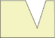
• For certain illumination directions, we can get both masking
and
shadow-
ing, as shown in Figure 27.14.
The detailed analysis of the effects of masking and shadowing, for various
distributions of microfacet orientations, is quite complex [TS67], but the analysis
predicts three important phenomena: The first is
backscattering,
in which some
incoming light from off-normal directions is reflected back toward the source;
the second is the off-specular peak—the peak value of the BRDF occurs not at the
mirror-reflection direction, but at a more-grazing (i.e., less normal) direction. The
third is that the value of the BRDF at grazing angles remains finite, which is in
accord with experimental observation, but not with prior microfacet models that
didn't account for masking and shadowing.
By the way, it's worth experimenting with a piece of ordinary office paper to
see how very specular are the near-grazing-angle reflections from a supposedly
matte surface. If in front of your face you hold a piece of paper by its bottom edge
so that the top falls down, forming a “hill” that you can look across, and then you
look at some fairly bright scene (the view out an office window on a sunny day
works well), you can see quite distinct features reflected in the paper at or near the
silhouette edge.
Figure 27.14: Incoming light
misses the bottom part of the
right-hand side of the V groove,
which is shadowed (right-
pointing red dashed ray); some
of the light reflected from that
right-hand side is masked by
the left-hand side (left-pointing
green dashed ray). (Courtesy
of Ephraim Sparrow, “Theory
for Off-Specular Reflection from
Roughened Surfaces” by K.
Torrance and E.M. Sparrow. It
was printed in
Journal of the
Optical Society of America
,Vol.
57, No 9, 1105-1114, September
1967. Redrawn.)