Graphics Reference
In-Depth Information
2
1
0
0
1
2
0
0.5
1
3
1.5
2
2.5
4
3
3.5
2
1
0
0
1
2
0
0.5
1
1.5
3
2
2.5
4
3
3.5
2
1
0
0
1
2
0
0.5
1
3
1.5
2
2.5
3
4
3.5
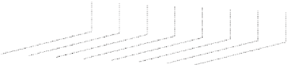
Figure 23.1: (Top) A Bézier patch drawn with the collection of curves t
→
S
(
s
,
t
)
for several
values of s between 0 and 1. (Middle) The same patch, drawn with the curves s
→
S
(
s
,
t
)
for several values of t. (Bottom) The same surface, drawn colored by height. In the top two
drawings, the control mesh Q
ij
(
0
≤
i
,
j
≤
3
)
is shown.
The shape of the surface patch we've just described is controlled by the loca-
tions of the control points
P
ij
. The surface passes through the four corner points
P
11
,
P
14
,
P
44
, and
P
41
. The points on the interior of each edge, like
P
21
and
P
31
,
control the shapes of the edges of the patch. For instance, the tangent plane to the
patch at
P
11
contains both the vector
P
21
−
P
11
,sothe
cross product of these two vectors is the surface normal at
P
11
. The four interior
control points determine the shape of the center region of the patch without influ-
encing the patch boundary. They do, however, affect the direction in which the
patch meets its boundary. If you plan to work with patches like this, you should
write a small interactive application in which you can manipulate each control
point to see its effect on the surface shape.
The surface we've just described is called a
bicubic tensor product patch,
because it's made by using products of basis functions, each of which is a cubic.
If, in the expression
b
i
(
u
)
P
ij
b
j
(
v
)
of Equation 23.3, we replaced
b
i
(
u
)
with
c
i
(
u
)
,
where
c
i
is the
i
th basis function for the Hermite curve, or the
i
th Catmull-Rom
basis, or the
i
th cubic B-spline basis, we'd get different kinds of tensor product
patches: The effects of the control points on the eventual shape would depend on
the kinds of basis functions used. You could make a patch that used Bézier curves
in one direction and Hermite in the other, for instance.
Just as we glued together curve segments to get longer curves, we can do
similar things to get larger surfaces. We can try to place two surface patches next
to each other so that they match up along a single edge. In the case of the Bézier-
based patches described above, the rightmost column of control points for one
patch must match the leftmost column of control points for the other, for instance.
This will guarantee that the surfaces join up (their joining edges consist of a single
P
11
and the vector
P
12
−