Graphics Reference
In-Depth Information
How do we specify the mapping from an object to texture space? The great major-
ity of standard methods start by assigning texture coordinates at mesh vertices and
using linear interpolation to extend over the interior of each mesh face. We often
(but not always) want that mapping to have the following properties.
•
Piecewise linear:
As we said, this makes it possible to use interpolation
hardware to determine values at points other than mesh vertices.
•
Invertible:
If the mapping is invertible, we can go “backward” from texture
space to the surface, which can be helpful during operations like filtering.
•
Easy to compute:
Every point at which we compute lighting (or whatever
other computation uses mapping) will have to have the texture-coordinate
computation applied to it. The more efficient it is, the better.
•
Area preserving:
This means that the space in the texture map is used effi-
ciently. Even better, when we need to filter textures, etc., is to have the
map be area-and-angle preserving, that is, an isometry, but this is seldom
possible. A compromise is a
conformal
mapping, which is angle preserv-
ing, so that at each point, it locally looks like a uniform scaling opera-
tion [HAT
+
00].
The following are examples of some common mappings.
•
Linear/planar/hyperplanar projection:
In other words, you just use some
or all of the surface point's world coordinates to define a point in texture
space. Peachey [Pea85] called these
projection textures.
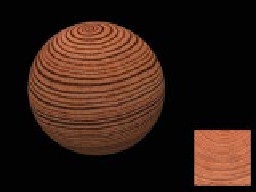
The wooden ball
in Figure 20.10 was made this way: The texture shown at the right on the
yz
-aligned plane was used to texture the ball by coloring the ball point
(
x
,
y
,
z
)
with the image color at location
(
0,
y
,
z
)
.
Figure 20.10: A wooden ball
made with a projection texture
shown at right (Courtesy of Kefei
Lei).
•
Cylindrical:
For objects that have some central axis, we can surround the
object with a large cylinder and project from the axis through the object
to the cylinder; if the point
(
x
,
y
)
projects to a point
(
r
,
,
z
)
in cylindrical
coordinates (
r
being a constant), we assign it texture coordinates
(
θ
θ
,
z
)
.
More precisely, we use coordinates
u
=
2
π
,
v
=
clamp
(
z
z
max
,
−
1, 1
)
, where
the clamp
(
x
,
a
,
b
)
returns
x
if
a
≤
≤
<
>
x
b
,
a
if
x
a
, and
b
if
x
b
.
•
Spherical:
We can often pick a central point within an object and project
to a sphere in much the same way we did for cylindrical mapping, and
then use suitably scaled polar coordinates on the sphere to act as texture
coordinates.
•
Piecewise-linear or piecewise-bilinear on a plane from explicit per-vertex
texture coordinates (UV):
This is the method we've said was most com-
mon, but it requires, as a starting point, an assignment of texture coordi-
nates to each vertex. There are at least four ways to do this.
-
Have an artist explicitly assign coordinates to some or all vertices. If
the artist only assigns coordinates to some vertices, you need to algo-
rithmically determine interpolated coordinates at other vertices.
-
Use an algorithmic approach to “unfold” your mesh onto a plane in
a distortion-minimizing way, typically involving cutting along some
(algorithmically determined) seams. This process is called
texture
parameterization
in the literature. Some aspects of texture parame-