Graphics Reference
In-Depth Information
CPU
Application
Scene-graph layer
IM layer
Extract
scene
from AM
Reduce
scene to the
minimal PVS
Reduce the
cost of
geometry
Calculate
efficient IM-
layer spec
Drive
GPU
GPU
GPU pipeline
GPU
optimization
GPU
rendering
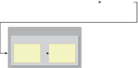
Figure 16.10: Sample distribution of AMIP responsibilities in an application using
retained-mode middleware.
Application
edits the
scene graph
Scene
graph
Synchronizer
Computed
IM-layer
cache
Platform updates
the acceleration data
structures/caches
BVH
IM-layer instruction
generator
VF culling logic
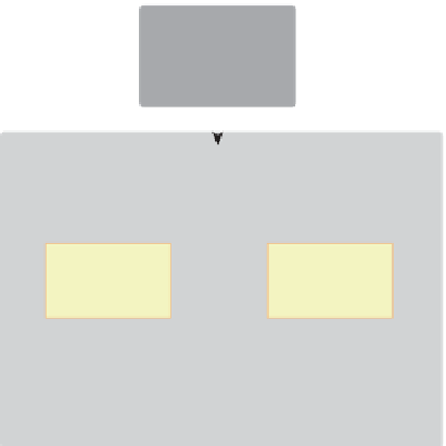
Figure 16.11: Abstract depiction of an RM layer providing two types of optimization dis-
cussed in Section 16.4.2 (view-frustum culling and IM-instruction reuse), showing the syn-
chronization logic that ensures the acceleration data structures (BVH and IM-instruction
cache, in this example) are updated when the scene graph is modified.
because the structures must be maintained as the scene graph is modified, requir-
ing sophisticated logic to avoid unnecessary invalidations (i.e., premature discard-
ing) of cached information, and to avoid the expense of wholesale regeneration of
the structures.
In addition to the CPU time allocated to maintaining these structures, there
is also a nontrivial CPU memory cost as well. At the end of this section, we'll
visit the issue of the runtime cost of scene-graph middleware and discuss the cost/
benefit tradeoffs.