Graphics Reference
In-Depth Information
efficient visibility algorithms and the opportunity to handle translucent surfaces in
more sophisticated ways.
15.6.6.3 Incremental Scanline Rasterization
For each row of pixels within the bounding box, there is some location that begins
the span of pixels covered by the triangle and some location that ends the span.
The bounding box contains the triangle vertically and triangles are convex, so
there is exactly one span per row (although if the span is small, it may not actually
cover the
center
of any pixels).
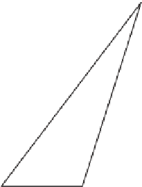
A scanline rasterizer divides the triangle into two triangles that meet at a hor-
izontal line through the vertex with the median vertical ordinate of the original
triangle (see Figure 15.15). One of these triangles may have zero area, since the
original triangle may contain a horizontal edge.
Figure 15.15: Dividing a triangle
horizontally at its middle vertex.
The scanline rasterizer computes the rational slopes of the left and right edges
of the top triangle. It then iterates down these in parallel (see Figure 15.16).
Since these edges bound the beginning and end of the span across each scan-
line, no explicit per-pixel sample tests are needed: Every pixel center between the
left and right edges at a given scanline is covered by the triangle. The rasterizer
then iterates up the bottom triangle from the bottom vertex in the same fashion.
Alternatively,
D
1
it can iterate down the edges of the bottom triangle toward
that vertex.
The process of iterating along an edge is performed by a variant of either the
Digital Difference Analyzer (DDA)
or Bresenham line algorithm [Bre65], for
which there are efficient floating-point and fixed-point implementations.
Pineda [Pin88] discusses several methods for altering the iteration pattern to
maximize memory coherence. On current processor architectures this approach is
generally eschewed in favor of tiled rasterization because it is hard to schedule for
coherent parallel execution and frequently yields poor cache behavior.
D
2
Figure 15.16: Each span's start-
ing point shifts
Δ
1
from that of
the previous span, and its ending
point shifts
Δ
2
.
15.6.6.4 Micropolygon Rasterization
Hierarchical rasterization recursively subdivided the
image
so that the triangle was
always small relative to the number of macro-pixels in the image. An alternative
is to maintain constant pixel size and instead subdivide the triangle. For example,
each triangle can be divided into four similar triangles (see Figure 15.17). This is
the rasterization strategy of the Reyes system [CCC87] used in one of the most
popular film renderers, RenderMan. The subdivision process continues until the
triangles cover about one pixel each. These triangles are called
micropolygons.
In addition to triangles, the algorithm is often applied to bilinear patches, that is,
Bézier surfaces described by four control points (see Chapter 23).
Subdividing the geometry offers several advantages over subdividing the
image. It allows additional geometric processing, such as displacement mapping,
to be applied to the vertices after subdivision. This ensures that displacement is
performed at (or slightly higher than) image resolution, effectively producing per-
fect level of detail. Shading can be performed at vertices of the micropolygons and
interpolated to pixel centers. This means that the shading is “attached” to object-
space locations instead of screen-space locations. This can cause shading features,
such as highlights and edges, which move as the surface animates, to move more
smoothly and with less aliasing than they do when we use screen-space shading.
Finally, effects like motion blur and defocus can be applied by deforming the final
shaded geometry before rasterization. This allows computation of shading at a rate
Figure 15.17: A triangle subdi-
vided into four similar triangles.