Graphics Reference
In-Depth Information
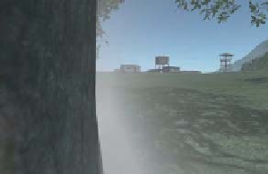
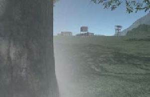
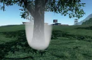
Figure 14.24: Box and ellipsoid fog volumes rendered by intersecting the view ray with an
analytic volume inside a pixel shader. (Credit: Courtesy of Carsten Wenzel, © Crytek)
limitations and provide manageable data sizes for the comprehension of human
modelers and programmers. That is, this decomposition simply follows classic
computer science and software engineering abstraction principles.
The data structure for maintaining the collection of objects in a scene is called
a
scene graph,
where “graph” refers to pointers that express relationships between
objects; you've already encountered a basic scene graph in the modeling hierar-
chy of Chapter 6, and the discussions of its traversal in Chapters 10 and 11. There
are many scene-graph data structures. Deep trees are well suited to modeling and
user-interface elements, where lots of fine-grained abstractions and a low branch-
ing factor match human design instincts. Relatively broad and shallow trees are
often well suited to rendering on hardware with many parallel processing units
and efficient object-level culling. Physical simulation often requires full graphs to
express cyclic relationships in the simulation.
More-or-less aligned with the three goals of modeling and interaction, ren-
dering, and simulation, there are three broad strategies for dividing the scene into
elements. Classic scene graphs and shading trees divide a scene into
semantic
ele-
ments. For example, a character model might contain a “hair” node that is a child
of a “head” node to enable easy coloring or replacement of hair. One might also
attach a “skin color” property to a root node at the character's torso that propa-
gates that color property throughout the model. Semantic nodes are very similar to
the cascading property schemes employed by text markup languages like HTML.
This is not surprising; markup effectively describes a scene graph for text layout
and rendering. Semantic scene graphics are nearly always directed acyclic graphs.
A child node typically inherits shading and simulation properties from its parent
in addition to a coordinate reference frame.
Physics scene graphs
typically express constraint relationships (edges)
between objects (nodes). These constraints are often joints. For example, a char-
acter's wrist is a constraint that defines the coordinate transformation between
the forearm and the hand. The constraints may be ephemeral; for example, a
bouncing ball temporarily is constrained to not penetrate the ground (and per-
haps experience limited lateral slip) on contact. Most dynamics systems include
both prerigged character and machine articulation graphs and context-dependent