Graphics Reference
In-Depth Information
We mentioned that there are other approaches to encapsulating the various trans-
formation operations needed in graphics, including basing them on coordinate
frames rather than linear transformations.
There's a particularly efficient way to create a
restricted
transformation library
in the case that we only want to describe
rigid
transformations of objects. This
eliminates all scaling—both uniform and nonuniform—and all nonaffine projec-
tive transformations. Thus, every transformation is simply a translation, rotation,
or combination of the two. There are two advantages of considering only such
transformations.
• There are no “degeneracies.” In the case of the
PointsToPoints
transfor-
mations we discussed earlier, there was a possibility of failure if the starting
points were not in general position. No such problem arises here.
• When we need to invert such a rigid transformation, no matrix inversion
procedure is needed, because the inverse of a rotation matrix
A
is its trans-
pose
A
T
.
There are disadvantages as well.
• We can no longer easily use a
PointsToPoints
specification for a transfor-
mation. The pairwise distances of the starting points must exactly match
those of the target points, because a rigid transformation preserves dis-
tances between points. It's impractical to try to specify target points with
this property, even when the source points are
(
0, 0
)
,
(
1, 0
)
, and
(
0, 1
)
,for
instance.
• We cannot make larger or smaller instances of objects in a scene using this
design. (A typical solution is to provide a method for reading objects from
afile
with a scale factor
so that you create a large sphere by reading a
standard sphere with a scale factor of 6.0, for instance.)
G3D, a package we'll use in Chapter 32 for the implementation of two ren-
derers, uses the rigid-motion approach. It contains a class
CFrame
(for “coordinate
frame”); the standard instance of this is the standard coordinate frame based at the
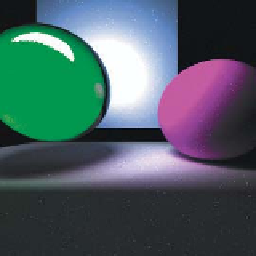
origin. The model for the scene in Figure 12.2 involves quite a lot of code, most
of which describes material properties, etc. The essence of the
geometric
part of
the modeling
3
is given in Listing 12.1, from which we've removed all modeling
of light sources and materials.
Figure 12.2: A simple scene.
Listing 12.1: Modeling a simple scene.
1
2
3
4
5
6
7
8
9
void World::loadWorld1() {
modeling of lights omitted
// A sphere, slightly to right, shiny and red.
addSphere(Point3(1.00f, 1.0f, -3.0f), 1.0f,
material specification
);
// LEFT sphere
addTransparentSphere(Point3(-0.95f, 0.7f, -3.0f), 0.7f,
material specifications
);
// And a ground plane...
addSquare(4.0, Point3(0.0f, -0.2f, -2.0f),
3. The camera is specified elsewhere in the program.