Graphics Reference
In-Depth Information
where the semicolon indicates that
u
1
is the first column of
the first
factor, etc.
The G3D library, which we use in examples in Chapters 12, 15, and 32, uses
rigid coordinate frames extensively in modeling, encapsulating them in a class,
CFrame
.
We've discussed affine transformations on a two-dimensional affine space, and
how, once we have a coordinate system and can represent points as triples, as in
x
=
xy
1
T
, we can represent a transformation by a 3
×
3matrix
M
.We
transform the point
x
by multiplying it on the left by
M
to get
Mx
. With this in
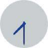
mind, let's return to the clock example of Chapter 2 and ask how we could start
from a WPF description and convert it to an image, that is, how we'd do some of
the work that WPF does. You'll recall that the clock shown in Figure 10.16 was
created in WPF with code like this,
Figure 10.16: Our clock model.
y
52
1
x
1
2
3
4
5
6
7
8
9
10
11
12
13
14
<Canvas ... >
<Ellipse
Canvas.Left=
"-10.0"
Canvas.Top=
"-10.0"
Width=
"20.0"
Height=
"20.0"
Fill=
"lightgray"
/>
<Control Name=
"Hour Hand"
.../>
<Control Name=
"Minute Hand"
.../>
<Canvas.RenderTransform>
<TransformGroup>
<ScaleTransform ScaleX=
"4.8"
ScaleY=
"4.8"
/>
<TranslateTransform X=
"48"
Y=
"48"
/>
</TransformGroup>
</Canvas.RenderTransform>
</Canvas>
5
y
9
y
Figure
10.17:
The
clock-hand
template.
where the code for the hour hand is
1
2
3
4
5
6
7
8
9
<Control Name=
"HourHand"
Template
="{StaticResource ClockHandTemplate}"
>
<Control.RenderTransform>
<TransformGroup>
<ScaleTransform ScaleX=
"1.7"
ScaleY=
"0.7"
/>
<RotateTransform Angle=
"180"
/>
<RotateTransform x:Name=
"ActualTimeHour"
Angle=
"0"
/>
</TransformGroup>
</Control.RenderTransform>
</Control>
and the code for the minute hand is similar, the only differences being that
ActualTimeHour
is replaced by
ActualTimeMinute
and the scale by 1.7 in
X
and
0.7 in
Y
is omitted.
The
ClockHandTemplate
was a polygon defined by five points in the plane:
(
1
)
(see Figure 10.17).
We're going to slightly modify this code so that the clock face and clock hands
are both described in the same way, as polygons. We
could
create a polygonal
version of the circular face by making a regular polygon with, say, 1000 vertices,
but to keep the code simple and readable, we'll make an octagonal approximation
of a circle instead.
−
−
1
)
,
(
−
0.2, 8
)
,
(
0, 9
)
,
(
0.2, 8
)
, and
(
0. 3,
−
0. 3,