Graphics Reference
In-Depth Information
6.6.3.5 Creating the Full Leg
Let's continue our bottom-up implementation by going up to the next level. The
“whole leg” is a composition of the lower leg (itself a composite) and the thigh
(a primitive). Let's first compose these two components to form a rigid locked
object, and then we'll attack the challenge of adding a knee joint.
As was the case for the lower leg, one of the subcomponents needs an instance
transform (i.e., the thigh needs to be raised 43 units in the
y
direction) and the other
is already at a suitable location. The resultant image is shown in Figure 6.47; the
XAML code is as follows:
1
2
3
4
5
6
7
8
9
10
11
12
13
14
<Model3DGroup x:Name=
"Leg"
>
<!- Build the lower-leg composite (same XAML shown earlier). ->
<Model3DGroup x:Name=
"LowerLeg"
> . . . </Model3DGroup>
<!- Instantiate and transform the thigh. ->
<GeometryModel3D Geometry=
"{StaticResource RSRCmeshThigh}"
Material=. . . >
<GeometryModel3D.Transform>
<TranslateTransform3D OffsetY=
"43"
/>
</GeometryModel3D.Transform>
</GeometryModel3D>
</Model3DGroup>
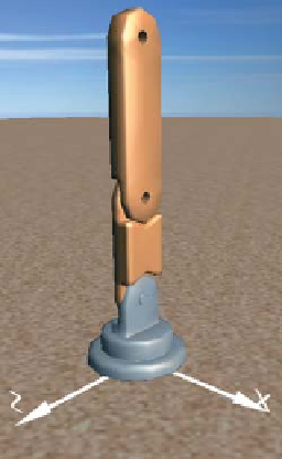
Figure
6.47:
Rendering
of
the
Inline Exercise 6.13:
Return to the lab, and select “Thigh” from the list of
models to examine that component in isolation. Then select the model “Whole
leg”. The undesired merging of the two subcomponents will be obvious. Repair
by adding an instance transform to the thigh to translate it on the
y
-axis. (If
you wish, you can jump straight to our solution by choosing “Whole leg auto-
composed” from the list of models.)
complete leg model.
6.6.3.6 Adding the Knee Joint
The leg is currently locked in a straight position. But, by adding a rotation trans-
formation to the lower leg, we can provide a “hook” that animation logic can use
to simulate bending at the knee.
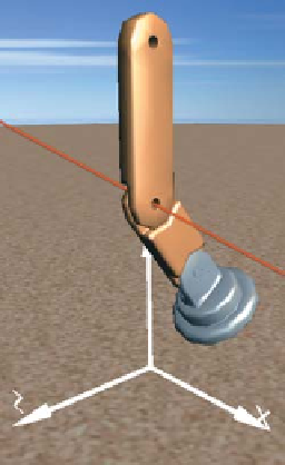
Figure 6.48 shows the leg in its canonical location at the origin, but with a 37
◦
rotation at the knee. (The invisible axis of rotation has been added to this rendered
image for clarity.)
The WPF element for expressing 3D rotation requires specification of the axis
and the rotation amount. The axis is configured via two parameters: an arbitrary
directional vector (e.g.,
100
T
representing any line that is parallel to the
x
-axis) and a center point lying on that vector (e.g., the center of the “knee” part
of the lower leg, which is
(
0, 50, 0
)
in the lower leg's coordinate system).
Figure 6.48: Result of specifying
a37
◦
rotation at the knee joint,
annotated with a red line through
the joint, parallel to the x-axis,
showing the axis of rotation.
Inline Exercise 6.14:
Return to the whole-leg model in the lab. Implement
the simulated knee joint by adding a rotation transform to the lower-leg com-
ponent. Set the rotation axis as needed, and then use the numeric spinner to
change the rotation amount to produce a knee-bend animation.