Graphics Reference
In-Depth Information
(Figure 6.43) to ensure that composing the two (to form the lower leg) requires
only translation of the shin, as shown in Figure 6.45. (We'll work through the
details of the lower leg construction in the next section.) No stretching/compress-
ing (scaling) or rotation actions are necessary. Similarly, the thigh is consistently
sized so that the full leg can be built by translating the thigh to connect it to the
top of the lower leg.
Note that a typical interactive 3D modeling environment makes it very easy to
build canonical, consistent atomic components, via features such as ruler overlays,
templates of common volumes, and snap-to-grid editing assistance.
Naturally, if your design incorporates subcomponents obtained from third
parties, inconsistencies can be expected, and additional transformations (e.g.,
resizing or reshaping via scaling) may be required to facilitate composing them
with the components you designed. Similar transformation-based adjustments
may be necessary when incorporating a completed composite model into an
existing scene. For example, if we wish to place our completed camel model
(which is well over 100 abstract units in height) into the pyramid scene we
constructed previously, we will have to take into account that our scene's world
coordinate system is a physical one with each unit representing 1 meter. Our
camel, if placed in that scene without scale adjustment, would be 100 meters tall,
towering over our 75-meter pyramid!
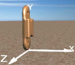
Figure 6.43: Rendering of the
shin model, at its canonical posi-
tion at the origin.
As a little hint for future work, it's always nice if you can build the parts of your
model in a way that makes it simple to place them in your scene. Aligning them
with coordinate axes or planes is a good start, but making their proportions
correct is also a good idea. It means that you can place the parts in the scene
using only translation, rotation, and
uniform
scaling (i.e., scaling by the same
amount in each axis). Such transformations turn out to be much easier to work
with than more general scaling transformations.
Figure 6.44: Rendering of a first
draft of a lower-leg model, con-
structed by composing the two
subcomponents without moving
them from their canonical posi-
tions at the origin of the coordi-
nate system.
6.6.3.2 Instantiating a Primitive Component
Once the primitive components have been designed and their meshes stored in the
resource dictionary, each one can be “test-viewed” by instantiating it alone in the
viewport, via creation of a
GeometryModel3D
element. The XAML shown below
adds an instance of the foot primitive to our desert-scene viewport:
1
2
3
4
5
6
7
<ModelVisual3D.Content>
<Model3DGroup>
Lights will be specified here.
<GeometryModel3D Geometry=
"{StaticResource RSRCmeshFoot}"
Material=... />
</Model3DGroup>
</ModelVisual3D.Content>
Note that the instantiated foot is not being transformed, so it will appear at the
origin of the world coordinate system of the scene, as you can see in Figure 6.42.
Inline Exercise 6.10:
Use the Model listbox, along with the turntable feature,
to examine the various primitive components of the camel in their canonical
positions at their local origins. For example, the shin in its canonical position
appears as shown in Figure 6.43.