Graphics Reference
In-Depth Information
and minute hands. Since the need for proper placement of a subcompo-
nent may be present anytime instantiation is performed, we tend to include
an instance transform on each subcomponent in our hierarchical design.
•A
joint transform
is used to simulate movement at a joint during anima-
tion. For example, the knee joint is implemented by a rotation transforma-
tion acting on the lower leg, and the hip joint is implemented by a rotation
transformation acting on the entire leg. In our clock application, we used
this to implement movement of the clock hands.
Now we demonstrate how XAML can be used to construct the model. The order
is bottom-up: first generating the primitive components (foot, shin, etc.) and then
composing the parts to create the higher-level components.
The activities involved in bottom-up construction are summarized in this table:
Intended Goal
Where
WPF Element/Properties
Specify the geometry
of a primitive
component
Resource section
MeshGeometry3D
element
GeometryModel3D
element
Name
property provides a unique
ID useful for animation and pick
correlation
Geometry
property points to the
corresponding
MeshGeometry3D
resource
GeometryModel3D.Transform
property can be used to specify
an instance transform and/or
joint transform, often in the form
of a
TransformGroup
Inside the content of a
viewport, as a direct
child of the
Model3DGroup
representing its parent in
the hierarchy
Instantiate a primitive
component
Inside the content of a
viewport, as a direct
child of the
Model3DGroup
representing its parent
in the hierarchy
Model3DGroup
element
Name
and
Model3DGroup.Transform
properties as described above
Construct a
composite component
6.6.3.1 Defining Geometries of Primitive Components
The design of each primitive component should be an independent task, with its
geometry specified in its own coordinate system, as we did for the clock hand
in Chapter 2. The abstract coordinate system in which an object is specified is
sometimes called the
object coordinate system
. For convenience, the component
should be at a canonical position and orientation—for example, at the origin, cen-
tered on one of the coordinate axes, resting on one of the three coordinate planes.
Choosing a physical unit of measurement is optional, but composing the parts
is simpler if the dimensions of components are
consistent.
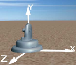
For example, we have
designed the foot as 19 units high (Figure 6.42) and the shin as 30 units high
Figure 6.42: Rendering of the
foot model, at its canonical posi-
tion at the origin.