Graphics Reference
In-Depth Information
,
,
,
n
,
n
,
,
n
u
5 458
u
5 08
u
5 908
cos
u
5 0
cos
u
5 1
cos
u
< 0.707
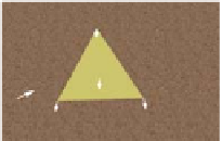
Figure 6.15: Brightness computed by Lambert's cosine law for three values of
θ
.
Figure 6.15 demonstrates this equation's effect on a single-triangle model, for
various values of
achieved by rotating the pyramid on an invisible turntable. In
the figure, the length of each dashed red vector depicts the intensity of the reflected
energy in its indicated direction, for the given value of
θ
. With perfectly diffuse
reflection, light is reflected with equal intensity in all directions, and therefore,
that length is a constant for any given value of
θ
. The locus of the endpoints of the
reflection vectors for all possible reflection angles is thus a perfect hemisphere in
the case of diffuse reflection. (In our 2D figure, of course, this envelope appears
as a semicircle.)
θ
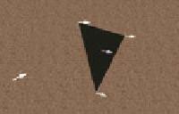
Figure 6.16: Rendering of the
pyramid with directional lighting,
with
θ
close to
90°
for the right-
most visible face.
This equation, being independent of viewing angle, cannot simulate glossy
materials such as metals and plastic that exhibit highlights at certain viewing
angles. Another oversimplification in the equation is an unrealistic lossless reflec-
tion of all incoming light energy when
=
0°. In reality, some amount of light
energy is absorbed by the material and thus is not reflected. Section 6.5 describes
a more complete model that corrects these and other problems.
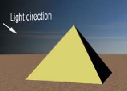
With directional lighting replacing ambient lighting, processed by the Lambert
lighting model, the results are more realistic, as you can see in the images in
Figures 6.16 and 6.17.
θ
Inline Exercise 6.6:
In the lab, activate the directional lighting by selecting
“directional, over left shoulder” and enabling turntable rotation. Observe the
dynamic nature of the lighting of the yellow front face; it may help to occa-
sionally pause/resume the turntable's motion. Observe the display of the value
of
θ
approaches and passes 90°. Select different models and examine the two-face
and full four-face models in this new lighting condition.
θ
and
cos
θ
, and note how the yellow face approaches zero illumination as
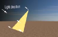
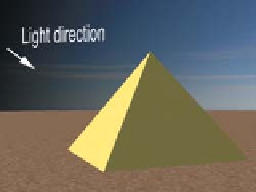
Figure 6.17: Rendering of the
pyramid with directional lighting,
with
θ
approximately
70°
for the
rightmost visible face.