Graphics Reference
In-Depth Information
We'll examine the characteristics and impact of point and other geometric light
sources in more detail in Section 6.5, but here let's start with a simplification: the
“degenerate case” of a point light source that is located at an infinite distance
from the scene. WPF distinguishes this kind of light source from geometric ones,
calling this a
directional light.
Its rays are parallel (with a constant
,asshownin
Figure 6.12), providing an approximation of light from an infinitely distant sun.
So, let's replace the ambient light source with a directional one. We'll specify
its color as full-intensity white, and its direction
as
1,
1
T
to simulate the
−
1,
−
,
1
,
2
,
3
sun's position being behind the viewer's left shoulder:
<DirectionalLight Color=
"white"
Direction=
"1, -1, -1"
/>
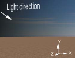
Surface
for this light (shown as a scene annotation in the lab and in
Figure 6.13) is at a 45° angle relative to all three axes, and when projected onto
the
xz
ground plane, it is a vector that travels from the (
The direction
Figure 6.11: Rays emanating
from a point light source in the
scene, striking points on a planar
surface at an infinite variety of
angles.
−
x
,
+
z
) quadrant to the
(
+
x
,
−
z
) quadrant.
Inline Exercise 6.5:
A static 2D image is not the best way to depict 3D infor-
mation like our light's
value, so we recommend that you use the lab to follow
along with this section's discussion. Select directional lighting, note the “Light
direction” annotation, and use the trackball-like mouse interaction within the
viewport to move around in the scene.
,
Figure 6.12: Rays emanating
from a directional light source,
infinitely distant from the pla-
nar surface, striking the surface's
points at identical angles.
As introduced in Section 1.13.2, for a completely diffuse surface like that of
our pyramid, the light is reflected with equal brightness in all viewer directions
and is therefore view-angle-independent. The brightness of the reflected light is
only dependent on how directly the incident light hits the surface. Figure 6.14
demonstrates how this directness is measured, by determining the angle
θ
between
and the surface normal
n.
The larger the value of
θ
, the more oblique the light
is, and thus the less energy reflected.
θ
and the incident light's intensity
I
dir
, the reflected intensity
is calculated by Lambert's cosine rule, which was introduced in Section 1.13.2:
I
=
I
dir
cos
Given the angle
θ
.
(6.1)
We've described light with the word “intensity” without a precise definition.
Intensity is a vague term, not even defined in the international standard for
units. Precisely defining “how much light is arriving here” turns out to be a bit
tricky. Chapter 14 gives some initial ideas, and Chapter 26 gives full detail.
It does seem as if getting “intensity” wrong ought to bring our work to a
stop, but the human visual system is coming to our rescue. It's mostly sensitive
to changes in light (either over time, or between nearby arriving-light direc-
tions), and exact magnitudes don't seem to matter much. In fact, if you take a
grayscale image with values between 0 and 1 and you replace each gray-value
g
with
g
2
or
g
3
and redisplay, the image is still perfectly understandable.
By the way, the word “brightness” is used to describe the
perception
of
light; it's a psychophysical measurement rather than a physical one. Many
papers in graphics have nonetheless used it as a proxy for “intensity.”
For now, treat “intensity” as meaning “some sort of measurement of light,
where bigger intensity means more light,” and wait until Chapter 26 to get the
whole story.
Figure 6.13: Our desert scene's
coordinate system with annota-
tion showing the direction of the
rays emanating from the direc-
tional light source.
,
n
u
Figure 6.14: The angle
, defined
as the angle between the incom-
ing light direction ray
and the
surface normal
n
.
θ