Graphics Reference
In-Depth Information
facing the front side. For example, consider how we are presenting the vertices of
the single triangle of our current model. In the
TriangleIndices
array, the three
indices into the
Positions
array are in the order 0, 1, 2. Thus, the vertices are
in the sequence
(
0, 75, 0
)
,
(
V
0
(0, 75, 0)
50, 0, 50
)
,
(
50, 0, 50
)
, which is a counterclockwise
ordering, as shown in Figure 6.5.
−
The XAML representation of this mesh is as follows:
V
1
V
2
1
2
3
<MeshGeometry3D x:Key=
"RSRCmeshPyramid"
Positions=
"0,75,0 -50,0,50 50,0,50"
TriangleIndices=
"0 1 2"
/>
Figure 6.5: Identification of the
front side of a mesh triangle
via counterclockwise ordering of
vertices.
This mesh specification appears in the resource section of the XAML, and thus
is similar to a WPF 2D template resource in that it has no effect until it is used
or instantiated. So the next step is to add the 3D object to the viewport's scene by
creating an XAML element of type
GeometryModel3D,
whose properties include
at least the following.
• The geometry specification, which will be a reference to the geometry
resource we created above.
• The material specification, which is usually also a reference to a resource.
The material describes the light-reflection properties of the surface; WPF's
materials model provides approximations of a variety of material types, as
we shall soon see in Section 6.5.
Let's keep things basic for now, and define a basic solid-yellow material
resource, earmarked for the front side of each surface, giving it a unique key for
later referencing:
1
2
<!- Front material uses a solid-yellow brush ->
<DiffuseMaterial x:Key=
"RSRCmaterialFront"
Brush=
"yellow"
/>
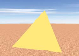
We now are ready to create the element that will add this single-triangle mesh
to our scene. We place this XAML as a child of the
Model3DGroup
element:
Figure 6.6: First triangle's front
side rendered using a uniformly
yellow material.
1
2
3
<GeometryModel3D
Geometry=
"{StaticResource RSRCmeshPyramid}"
Material=
"{StaticResource RSRCmaterialFront}"
/>
Our image of the model now appears as shown in Figure 6.6.
Inline Exercise 6.2:
In the lab, select the “Single face” option in the model
drop-down list. If you wish, click on the XAML tab to examine the source
code generating the scene. Activate the turntable to rotate this triangle around
the
y
-axis.
Figure 6.7: First triangle's back
side, invisible due to lack of spec-
ification
If we were to rotate this triangular face 180° around the
y
-axis, to examine its
“back side,” we would obtain the puzzling image shown in Figure 6.7.
of a
material
for the
back side.
The triangle disappears due to a rendering optimization: WPF by default does
not render the back sides of faces. This behavior is satisfactory for the common
case of a “closed” object (such as the pyramid we intend to construct) whose
exterior is composed of the front sides of the mesh's triangles. For such a closed
figure, the back sides of the triangles, whose surface normals point toward the
object's interior, are invisible and need not be rendered.