Graphics Reference
In-Depth Information
Chapter 4
Now that you are familiar with some aspects of WPF and have seen our promised
test bed in use in building the Dürer renderer, we show you the details of the
test bed—a framework for testing out ideas in graphics without a huge amount
of overhead. There are actually two of these: one for 2D and one for 3D. This
chapter introduces the 2D test bed; more complete documentation, along with
the 3D test bed, are available on the topic's website. We refer to these as test
beds because they resemble the test apparatus that an electrical engineer might
use: a collection of instruments, power sources, and prototyping boards on which
various circuits can be assembled and tested. Our design aims are modest: We
want a basic framework in which it's easy to write and debug simple programs.
Ease of debugging is favored over speed; simplicity is favored over generality.
Throughout this topic, we present exercises that involve writing small
programs designed to investigate some subject that you've studied. For instance,
when we discuss the mathematical modeling of shapes, we start with polygons
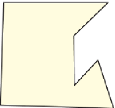
and show how to make curves shaped by them. Figure 4.1 shows an example of
this: You can take a closed
polyline
—a connect-the-dots sequence of segments in
a plane—and perform a
corner-cutting
operation on it in which each segment is
divided into thirds, the first and last thirds of each segment are removed, and the
remaining segments are joined up in sequence.
It appears that if you do this repeatedly, the resultant polyline becomes increas-
ingly smooth, approximating a smooth curve. While it's possible (and valuable)
to analyze this process mathematically, we believe that a picture is worth a thou-
sand words and that interaction is worth many thousands more. We therefore give
you the tools to answer a variety of questions you may have—such as whether the
curve will
always
get smoother, whether there are starting polylines that result in
curves that have sharp corners, regardless of the number of iterations, and what
happens if you keep the middle
half
of each segment instead of the middle third—
so that you can get a visceral understanding of the process. At the same time, writ-
ing programs to implement such ideas frequently helps you understand subtleties.
Figure 4.1: Top: A polyline in the
plane. Middle: Each segment has
been divided into thirds, and the
division points have been marked
with dots. Bottom: The middle
thirds of the segments are con-
nected together to form a new,
smoother polyline.
81


