Graphics Reference
In-Depth Information
lens in such a way that it blocks only some of the rays in the pencil from reaching
the aperture, then only some of the light leaving the point toward the aperture will
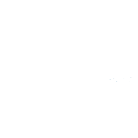
actually form an image. In this case, depicted in Figure 36.23,
Q
only receives
partial coverage from
P
.
If there are no occluders but
P
is out of focus, then the light from the pencil
originating at
P
is spread over a region on the image plane. Point
Q
now receives
only a fraction of the light that it did in the in-focus case, so it now receives partial
coverage by
P
.
Point in
scene
P
Occluder
Of course, a point may have partial coverage because it is both out of focus
and partly occluded, and other sources of partial coverage can combine with these
as well.
Note that in a sense any point is partially occluded by the camera case and
finite lens—there are light rays from a scene point that would have struck the
aperture had the lens only been larger. For a lens camera it is always necessary
to know the size of the lens to compute the total incident light. The total light
is proportional to the partial coverage, but we must know the size of the lens to
compute the total power.
One way to compute partial coverage due to defocus is to sample visibility
at many rays within the pencil and average the result. Because all the rays of the
pencil share a common origin, there is an opportunity to amortize the cost of these
binary visibility operations. The
packet tracing
and
rasterization
algorithms dis-
cussed in Chapter 15 leverage this observation.
Lens
Point on image plane
Q
Figure 36.23: Partial occlusion
of the lens leads to partial occlu-
sion
of
the
single
point
P
at
point Q.
Just as real cameras have nonzero aperture areas, they also have nonzero exposure
times. This means that visibility can vary throughout the exposure. For any spe-
cific time, binary visibility may be determined between two points. The net visibil-
ity during an exposure will be the integral of that binary visibility over the expo-
sure period, during which primitives may potentially cross between the points,
producing an effect known as
motion blur.
For primary visibility in the presence
of motion blur, we must consider the fact that the points for which we are testing
visibility are on curves through space and time. This is easily resolved by per-
forming all tests in camera space, where the primary rays are static with respect to
time. Then we need only consider the motion of the scene relative to the camera.
Spatial data structures must be extended to represent motion. In particular, a
spatial structure needs to bound the extrusion of each primitive along its motion
path during the exposure. This step was not necessary for defocus because in that
case we were performing ray-intersection queries that varied only the rays, not the
triangles. When the triangles move with respect to each other a data structure built
for a single position is no longer valid. A common strategy is to first replace each
primitive with a conservative (and typically convex) bound on its motion. The
second step is then to build the hierarchy on those proxies rather than the primi-
tives themselves. When thin primitives rotate this can create excessively conser-
vative bounds, but on the other hand, this approach is relatively straightforward
to implement compared to considering the complex shapes that tightly bound
rotating primitives.
This strategy generalizes to simply considering ray casting as a “four-
dimensional” problem, where both rays and surfaces exist in a 4D space [Gla88].
The first three dimensions happen to be spatial and the fourth is temporal, but
mathematically one can frame both the ray-intersection problem and the spa-
tial data structure construction so that they are oblivious to this distinction. For