Graphics Programs Reference
In-Depth Information
endpoints of the line segments are attached to one another and will
move together.
15.
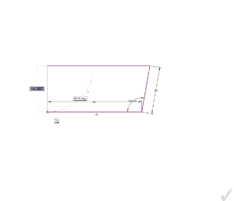
Click the mouse to connect the lines. See Figure 3.6.
16.
Press the Esc key to finish the Line tool.
FIGURE 3.6
The initial shape is done.
Now that you have your initial shape, you can modify it to be the correct shape
and size. Getting your sketch close to correct is good, but as long as you have the
elements you need, you can modify it to be correct.
Adding and Editing Geometric Constraints
Creating the sketch added sizes and created relationships between sketch elements.
At this point, you could easily turn this into a solid model.
What you really need, though, is a square centered on the center point of the
part. Now, you will make modifications to fix this and see some other options
along the way:
Certification
Objective
1.
Continue using the drawing from the previous exercise or make cer-
tain that the 2013 Essentials project file is active, and then open
c03-
01.ipt
from the
Parts\Chapter3
folder and double-click Sketch1 in
the browser to make it active.
When the sketch
(or elements of it)
are selected in the
Graphics window,
you can access
constraint visibility
through the right-
click context menu.
2.
On the status bar, click the Show All constraints icon, or simply press
the F8 key. Figure 3.7 shows the result.
This will display the relationships between the elements. The yellow
blocks at the corners represent coincidence.
3.
Hover over the Perpendicularity icon in the lower-left corner, and it
will highlight the segments that are constrained.


Search WWH ::

Custom Search