Graphics Programs Reference
In-Depth Information
10.
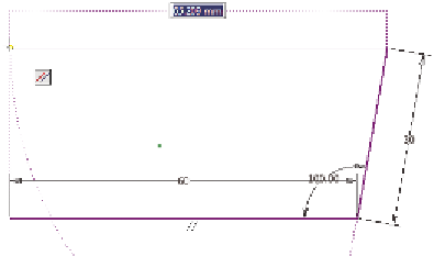
Enter a value of
30
for the next segment, and use the Tab key to set
the angle to 100. You might have to pan or zoom to see the second
segment.
11.
Click in the Design window to place the new segment, and notice the
new dimensions that appear, as shown in Figure 3.4.
FIGURE 3.4
Adding values to dimensions creates
the parametric dimensions on the fly.
12.
Move your cursor to the left. Look for an icon that shows the new
segment is parallel to the first. Move to the left until you also see a
dotted “inference” line that aligns you with the starting point of the
first segment.
13.
Click the mouse when your line is parallel with an aligned endpoint,
as shown in Figure 3.5.
FIGURE 3.5
If you don't specify a dimension value,
no dimension is added to the sketch.
14.
Now move your cursor down to the original start point. The point
will highlight, and a glyph will appear, showing that there will be a
connection called
coincidence
between the points, which means the


Search WWH ::

Custom Search