Graphics Programs Reference
In-Depth Information
5.
Right-click the 14.00 dimension in the baseline set, and select Detach
Member from the context menu.
You can also delete a
member and use the
Arrange tool to bring
the dimensions back
in order.
6.
Double-click the 14.00 dimension.
7.
When the Edit Dimension dialog box opens, select the Precision And
Tolerance tab.
8.
In the Precision field on the right, use the Primary Unit drop-down,
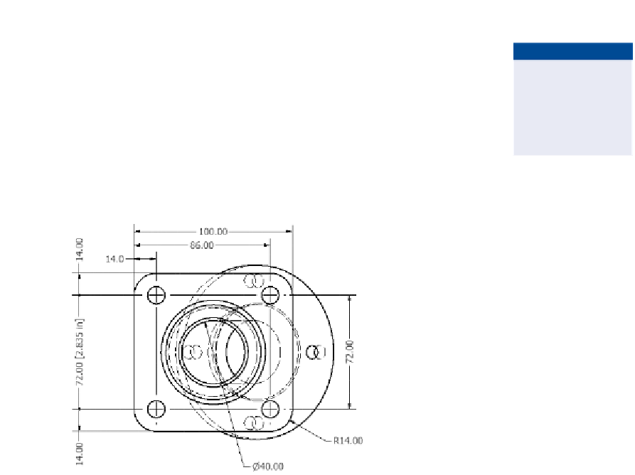
and change the value to 1.1. Click OK. See Figure 2.28.
FIGURE 2.28
The dimensions can still be edited
after being placed.
The Edit Dimension dialog box offers a lot of options that I didn't cover in the
exercise, including tolerancing, fits, and even the ability to define an inspection
dimension.
The Hole and Thread Notes Tool
Inventor's part modeling tools give you the ability to define holes by thread and
their clearances for fasteners based on standards. To document these features,
use the Hole and Thread note tool, which extracts the information directly from
the feature.
Certification
Objective
1.
Make certain that the 2013 Essentials project file is active, and then
open
c02-17.idw
from the
Drawings\Chapter2
folder.
2.
Zoom in on the rotated auxiliary view in the upper left of the drawing.
3.
Find and start the Hole and Thread tool in the Feature Notes panel of
the Annotation tab.

Search WWH ::

Custom Search