Graphics Programs Reference
In-Depth Information
next step does the same thing, but by using the lines of code, it can be set up
very quickly.
1.
Continue using the
c15-06.iam
file from the previous exercise.
2.
In the iLogic Browser, right-click Drawer Size Control rule, and
select Edit Rule.
3.
Below the comment added in the previous section, type the following:
Parameter (“c15-21:1,”
“drawer_width”) = drawer_width
.
This statement simply says that the parameter named drawer_width
in the first assembly instance of the model named c15-21 gets its value
from the parameter named drawer_width in this assembly.
4.
Highlight that line, copy it to the clipboard, and paste a copy directly
below this one. It's a good idea to create a little space between lines.
5.
In the new line, change the word
width
to
height
so that it reads as
follows: Parameter (“c15-21:1,” “drawer_height”) = drawer_height.
Now, you've linked the height value of the assembly to the part.
Next, you need to leverage these values with the edge banding. Even
if you don't set up every parameter name in one component to match
up to the parameter names of another, you can still create effective
relationships between them.
6.
Paste the text into the window again and modify it to say the following:
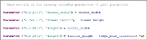
Parameter (“c15-22:1,” “length”) = drawer_width.
The last stage in the rule has an extra step because you need to
subtract the thickness of the edge band, as you did when creating
the equation in the Parameters table.
7.
Create a new row of text to read as follows: Parameter (“c15-23:1,”
“length”) = (drawer_height - (edge_band_thickness) *2).
8.
Compare your rules to Figure 15.28, and click OK to save the rule
you've created.
FIGURE 15.28
Rules can create connections between
components.

Search WWH ::

Custom Search