Graphics Programs Reference
In-Depth Information
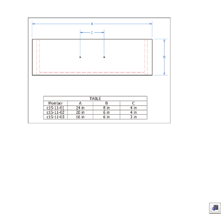
FIGURE 15.21
The completed table showing the values for
the table dimensions
12.
Find the Parts List tool on the Annotate tab in the Table panel, and
click it.
13.
Click the drawing view of the assembly, and then click OK to place a
standard parts list under the assembly view.
14.
Double-click the parts list to open the editing dialog box.
15.
Click the Member Selection icon.
16.
In the Select Member dialog box, click all three versions of the iAssembly,
and click OK.
17.
Click the Column Chooser button, and remove the Description column
from the Selected Properties list.
18.
Click OK twice to update the parts list on the drawing.
As Figure 15.22 shows, the parts list contains the quantity of the
parts in rows and the configuration of the assembly in columns.
For many years, “family parts” or configurations of an assembly could be included
on 2D drawings only as tables. These tables could be very complex and include a lot
of information, and if a change to a family member occurred, it was easy to miss it
in the drawing.

Search WWH ::

Custom Search