Graphics Programs Reference
In-Depth Information
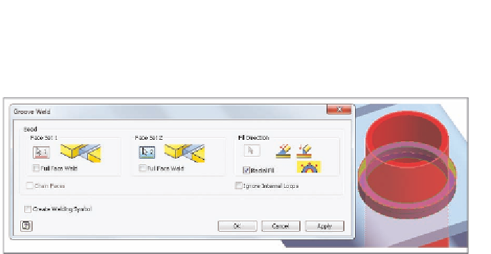
The groove weld could be left as is, or it could be added as part of a manufac-
turing process that would now add another weld to it.
FIGURE 12.7
The preview of the groove weld
Adding a Cosmetic Weld and Weld Symbols
The fillet and groove are the most common welds and therefore generate physi-
cal geometry to represent them, but there are many types of welds that need to
be documented and considered in the weldment. A cosmetic weld will apply a
weld to an assembly but will not build the geometry itself.
1.
Make certain that the 2013 Essentials project file is active, and then
open
c12-05.iam
from the
Assemblies\Chapter12
folder.
2.
Access the Weld tools by clicking Welds from the marking menu or
from the Process panel on the Weld tab.
3.
In the Weld panel of the Weld tab or from the marking menu, click
the Cosmetic Weld tool.
4.
In the cosmetic weld, set the Area value to 6 mm^2.
5.
Leave the Extents set to All, and select the Create Welding Symbol
check box.
This expands the dialog box and allows you to select the specific
type of weld that the cosmetic weld will represent. The default is a
fillet weld for the opposite side.
6.
Click the Swap Arrow/Other Symbols icon to make the fillet weld for
the Arrow side.
7.
Make sure the Bead selection icon is active, and click the edge shown
in Figure 12.8.
8.
Click OK to place the weld, which is represented by a highlighted
edge and the weld symbol shown in Figure 12.9.

Search WWH ::

Custom Search