Graphics Programs Reference
In-Depth Information
6.
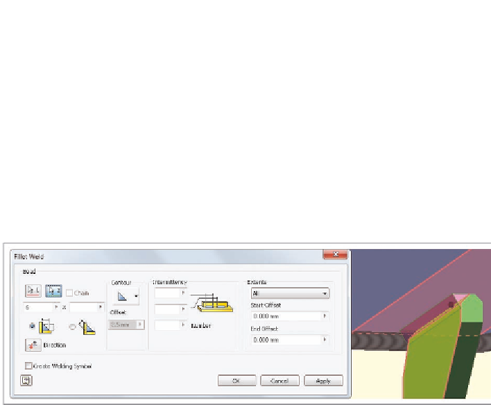
Set the first fillet value to 6 mm per the weld calculation done previ-
ously in this chapter.
7.
Click Apply to generate the fillet weld.
8.
Deselect the Chain option.
9.
For the first selection, click the face on the blue tube adjacent to the
green gusset.
10.
Switch to the second selection set, and click the triangular side and
the chamfer surface shown in Figure 12.5.
FIGURE 12.5
A weld filling the gap left by a chamfer
11.
Click OK to place the weld.
Because you selected the side and chamfer face on the gusset, the
weld fills in all of the space. Selecting only the blue tube and the side
of the gusset could still generate a weld, but it would leave a space.
One last touch is needed to make the weld look better.
12.
In the Weld panel of the Weld tab, find the End Fill tool, and start it.
The bare ends of the weld bead should highlight. If they do not,
click them.
13.
Click one of the ends of the bead, and an image will be added to it, as
shown in Figure 12.6.
14.
Press the Esc key to end the End Fill tool.
Now you've added fillet welds to the assembly. These welds do not require any
new part files to maintain them in the assembly.

Search WWH ::

Custom Search