Graphics Programs Reference
In-Depth Information
2.
Click the Convert to Weldment tool on the Convert panel of the
Assemble tab.
3.
Click Yes when prompted that you will not be able to revert this data
to a basic assembly.
After you confirm the conversion, the Convert To Weldment dialog
will appear for you to input specific information about the standards
and structure of the weldment.
4.
Set Weld Bead Material to Welded Steel Mild using the drop-down.
5.
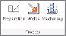
Click OK to add the Weld tab to the Ribbon (Figure 12.1), and popu-
late the Browser with a Preparations, Welds, and Machining group.
Once converted, a
weldment cannot be
returned to a regular
assembly.
FIGURE 12.1
The three
additional states of a weldment
The assembly is still an assembly; it will just be treated differently in the BOM
and have access to new tools.
Calculating a Fillet Weld
The design accelerators covered in Chapter 8, “Advanced Assembly and
Engineering Tools,” focused on tools that generated components. There is
another class of tools associated with design accelerators; they are the calcula-
tors. The Inventor Weld Calculator tools can calculate several types of welds and
solder joints.
1.
Make certain that the 2013 Essentials project file is active, and then
open
c12-02.iam
from the
Assemblies\Chapter12
folder.
2.
Expand the Weld Calculator tool in the Weld panel on the Weld tab.
3.
Click the Fillet Weld Calculator (Plane) tool.
The goal is to keep the weld at the base of the blue arm less than
7 mm. The calculator helps you determine whether this is reasonable.
4.
Set the weld form to an all-around rectangle.
5.
Set the weld loads to be the bending force parallel with the neutral
axis of the weld group.


Search WWH ::

Custom Search