Graphics Programs Reference
In-Depth Information
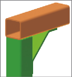
FIGURE 11.8
Trim to Frame
will accommodate the sizes of both
frame members for a clean overlap.
The Trim/Extend Tool
When frame members are placed on the skeleton, they're often overlapping or
might fall short of other members they need to butt against. This end treatment
allows you to select several members and terminate them at a selected face, whether
it means trimming or extending them.
1.
Make certain that the 2013 Essentials project file is active, and then
open the
c11-06.iam
file from the
Assemblies\Chapter11
folder.
2.
Switch the Ribbon to the Design tab, and start the Trim/Extend tool
from the Frame panel.
3.
When the dialog box opens, click the two longest members at the
base. Once they're selected, right-click and click Continue from the
context menu to select the trimming face.
4.
Click the face that the two selected segments intersect, as shown in
Figure 11.9, and then click OK.
You must select model faces for the trimming surface. The model face can be
a face on the skeleton if it is a solid model.
Creating Notches
For more complex joints between frame members, you can cut one member
with the shape of another.
1.
Make certain that the 2013 Essentials project file is active, and then
open the
c11-07.iam
file from the
Assemblies\Chapter11
folder.

Search WWH ::

Custom Search