Graphics Programs Reference
In-Depth Information
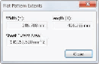
FIGURE 10.26
The Flat Pattern
Extents dialog box reports the material
needs of the part.
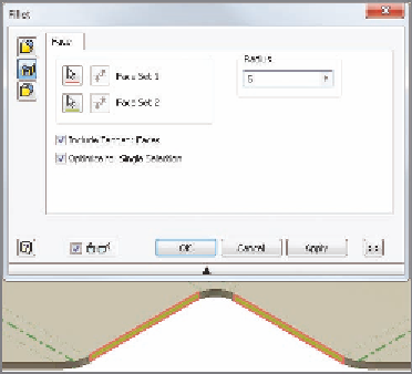
12.
Start the Fillet tool by pressing F (click OK to modify the flat pattern),
and set it to a face fillet.
13.
Click the two sides of the part shown in Figure 10.27, and set the radius
to 5 mm.
14.
Click OK to place the fillet in the flat pattern.
FIGURE 10.27
You can add features like
fillets to the flat pattern.
The fillet that was added appears on drawings of the flat pattern but does not
propagate back to the 3D model. Features added to the flat pattern are specifically
for the use and benefit of the manufacturing process.
Documenting Sheet Metal Parts
The ability to create documentation in the drawing view that you've seen with
other solid models works just as well for sheet metal components, but they need
Search WWH ::

Custom Search