Graphics Programs Reference
In-Depth Information
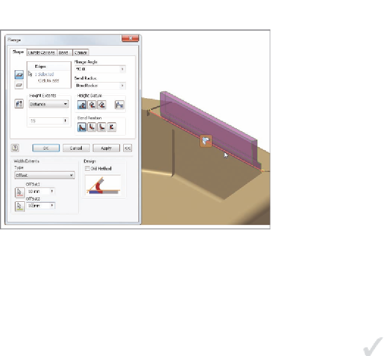
FIGURE 10.9
Adding a flange with the ends offset from the edge length
The angle of a new flange and how it is developed in the footprint of the exist-
ing parts are all important options worth experimenting with when using the
Flange tool.
Building from the Middle
At times, you might need to build faces in space or from projections from other
parts in the assembly. Faces can be created in space with no connection to the
rest of the part, but eventually they will need to be attached to the rest of the
part. The Bend tool can help you do that using more than one workflow.
Certification
Objective
1.
Verify that the 2013 Essentials project file is active, and then open
c10-04.ipt
from the
Parts/Chapter10
folder.
2.
On the Sheet Metal tab, start the Bend tool from the Create panel.
3.
Click one of the long edges of the red Face feature and then an edge
on the nearest flange of the main body.
The preview shows a feature that bridges the selected edges and
cuts into the flange on the main part.
4.
Click the Full Radius option in the Bend dialog box. Notice that the
preview shows a feature that is tangent to both faces.
5.
Return to the 90 Degree option, and click the Flip Fixed Edge option.
Your screen should look like Figure 10.10.
This bases the geometry on the selected edge of the main part.


Search WWH ::

Custom Search