Graphics Programs Reference
In-Depth Information
Adding a Lip
A lip allows the plastic parts to remain aligned so the form remains consistent.
You can use other sketched features, such as the Sweep tool, to make the geome-
try, but the Lip tool makes it easier to adjust things like draft and to recess edges.
1.
Verify that the 2013 Essentials project file is active, and then open
c09-04.ipt
from the
Parts\Chapter9
folder.
2.
Rotate the front body so that you can see the back side of it.
3.
Start the Lip tool. It is on the 3D Model tab in the Plastic Part panel.
4.
In the dialog box, make sure the option on the left is set to Lip, and
then select the Pull Direction check box.
This changes the dialog box options for constructing the lip feature.
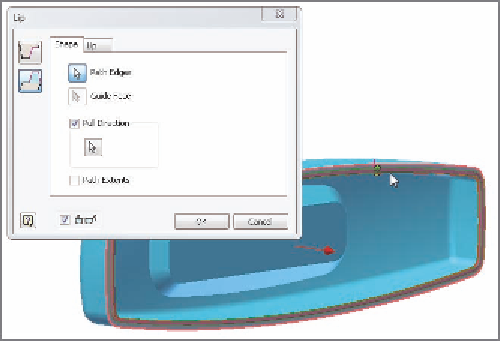
5.
Click the flat face around the perimeter of the part to set the Pull
Direction option.
6.
Once the direction is selected, click the inner edge of the perimeter
for the path edges, as shown in Figure 9.5.
FIGURE 9.5
Selecting model edges to place a lip feature
7.
Click the Lip tab in the dialog box, and review the options.
8.
Click OK to place the feature using the default options. The result is
shown in Figure 9.6.


Search WWH ::

Custom Search