Graphics Programs Reference
In-Depth Information
Using a Linear Hole Placement
Linear hole placement requires selecting a face on which to place the hole. Once
you've done that, you can simply click OK to generate the feature. You can also
click one or two edges to locate the hole relative to them using parametric dimen-
sions placed for you.
1.
Make certain that the 2013 Essentials project file is active, and then
open
c07-07.ipt
from the
Parts\Chapter7
folder.
2.
Start the Hole tool by selecting it from the Modify panel on the 3D
Model tab. It is also on the marking menu.
3.
Set the hole class to Counterbore. Set the hole type to Clearance
Hole, and then set the standard to be ANSI Metric M Profile. Set the
fastener type to Socked Head Cap Screw, and set the size to M4 and
the termination to Through All.
4.
Click the top face of the plate near the notch.
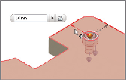
5.
Click the edges shown in Figure 7.11, and set their offset values to
14 mm.
6.
Click OK to place the hole.
FIGURE 7.11
Placing the hole
based on the edges of the part
The diameter and depth of the counterbore and the size of the hole were all
determined based on standards for the fastener that will go through it. With the
hole in place, you can replicate it using the Rectangular Pattern tool.
Creating a Rectangular Hole Pattern
Let's create a series of these holes. On this part, the holes will be in a pattern where
the two directions are perpendicular, but the pattern can go in any two directions.
Certification
Objective
1.
Make certain that the 2013 Essentials project file is active, and then
open
c07-08.ipt
from the
Parts\Chapter7
folder.


Search WWH ::

Custom Search