Graphics Programs Reference
In-Depth Information
2.
Start the Loft tool from the Create panel of the 3D Model tab.
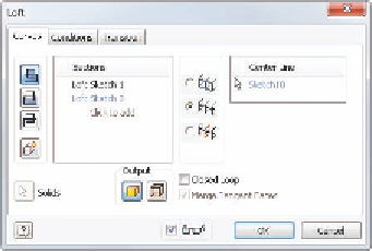
The dialog box that opens (Figure 7.3) displays two primary areas for
sections and rails or centerlines. As you click geometry, the selected
parts will appear in these windows.
FIGURE 7.3
The Loft dialog box showing
the Center Line path option
When you start the tool, it will look to select sections first.
3.
For the first profile, click the red sketch on the rim of the wheel seg-
ment. It is labeled as Loft Sketch 1 in the browser, or you can select it
from the Design window.
4.
Click the 3D sketch (Loft Sketch 2) for the second profile.
5.
Between the Sections and Rails groups are the Rail options. Set the
option for Center Line. This will also change the Loft tab displayed in
the dialog box to a Curves tab.
6.
On the Curves tab, click where it says
Select a sketch
in the Center
Line group. Select the sketched path.
As you've seen with other sketched features in Inventor, a preview
will appear when all of the elements needed to define it are satisfied.
7.
Once a preview appears like Figure 7.4, click OK to create the feature.
8.
Drag the end-of-part marker to the bottom of the browser, or right-click
and select the Move EOP To End option from the Context menu. The
model will generate the pattern of the full solid model. See Figure 7.5.
The loft has created a connection between the hub and rim of the wheel. The
minimum of two profiles were used, but you can add as many profiles as you
need to accurately develop the shape you want. One loft option makes it possible
to control the area of each section for more advanced designs.


Search WWH ::

Custom Search