Graphics Programs Reference
In-Depth Information
To define the second profile, you need to build a plane on a curved face:
1.
Make certain that the 2013 Essentials project file is active, and then
open the
c07-01.ipt
file from the
Parts\Chapter7
folder.
2.
Double-click Loft Sketch 2 in the browser to edit the sketch.
3.
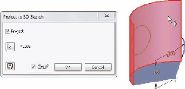
Locate the Project Geometry tool in the Draw panel of the Sketch
tab. Expand it, and start the Project to 3D Sketch tool.
4.
In the dialog box, select the Project check box (Figure 7.1), click the
curved face, and click OK.
This will create a new 3D sketch, applying the circle to the cylin-
drical face.
5.
Click Finish Sketch in the Ribbon or use the marking menu.
A 3D sketch can also
be created on its
own without the use
of a 2D sketch.
FIGURE 7.1
Projecting a 2D sketch onto a
3D face
Creating the 3D sketch has given you a second profile for your loft. Now you
need a path for the two profiles to transition along.
Defining a Loft Path Between Points
To define a loft along a path, you must create a minimum of three sketches. You
need a beginning profile and an end profile, as well as another sketch to define
the path along which the shapes will transition from one to the other.
The type of path you will be using must be built between existing points,
ensuring alignment of the profiles you will loft between.
1.
Make certain that the 2013 Essentials project file is active, and then
open
c07-02.ipt
from the
Parts\Chapter7
folder.
2.
Create a new sketch by selecting the XZ plane in the Origin folder of
the browser and clicking the Create Sketch icon that appears in the
Design window.


Search WWH ::

Custom Search