Graphics Programs Reference
In-Depth Information
There are also other ways to dimension the part.
Placing Ordinate Dimensions and
Automated Centerlines
Ordinate
dimensions (like baseline dimensions) can be placed either as individu-
als or as a set. The Ordinate Set option keeps the members styled as a set and
also automatically does some spacing of the dimensions.
1.
Verify that the 2013 Essentials project file is active, and then open
c06-17.idw
from the
Drawings\Chapter6
folder.
2.
Right-click within the boundary of the view, and select Automated
Centerlines from the context menu.
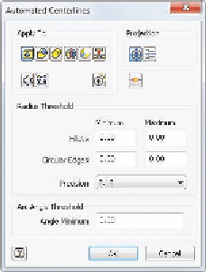
The Automated Centerlines dialog box (Figure 6.25) allows you to
select whether to include cylindrical extrusions or faces that have
a radius, and you can also choose whether to select objects with an
axis that is normal or parallel to the view.
FIGURE 6.25
The Automated
Centerlines dialog box
3.
Keep the defaults, and click OK to place the centerlines.
4.
Locate the Ordinate dimension tool in the Dimension panel on the
Annotate tab, expand it, and select the Ordinate Set tool.
5.
In the status bar, notice the prompt to click an origin point. Click the
center mark of the large hole in the lower-right corner of the part.
6.
Then, click the vertical edges of the part shown in red in Figure 6.26
and the center marks highlighted with green dots.

Search WWH ::

Custom Search