Graphics Programs Reference
In-Depth Information
The dotted lines and circle that appear in the sketch have an over-
ride applied to them: Construction. This prevents them from being
recognized as profiles by the 3D features but allows them to be used
to construct other things. In this case, you'll use them for the loca-
tion of the center points for holes. The corners of the square have
an override applied as well. This will make the Hole tool find them
automatically.
2.
Start the Hole tool. As mentioned, four locations will be selected.
3.
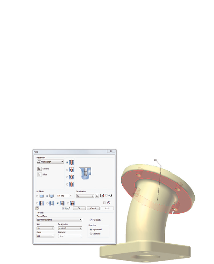
Set the type to Tapped Hole, the thread type to ISO Metric profile,
and the size to 10. Select the Full Depth check box for the threads.
4.
Change the termination to To, and click the lower side of the cylindri-
cal face so the holes stop there. See Figure 3.31.
5.
Select OK to complete the hole.
FIGURE 3.31
Hovering over an obscured object will eventually
cause a drop-down to appear, allowing you to select it.
Now, your part is complete. You've used a lot of different features and a num-
ber of different techniques. You'll use even more features in Chapter 7 to create
more complex geometry. The exact tools you will use depend on what it is you
need to accomplish.
Search WWH ::

Custom Search