Graphics Programs Reference
In-Depth Information
4.
Now, click the Axis icon on the mini-toolbar to let Inventor know
you're done selecting profiles.
5.
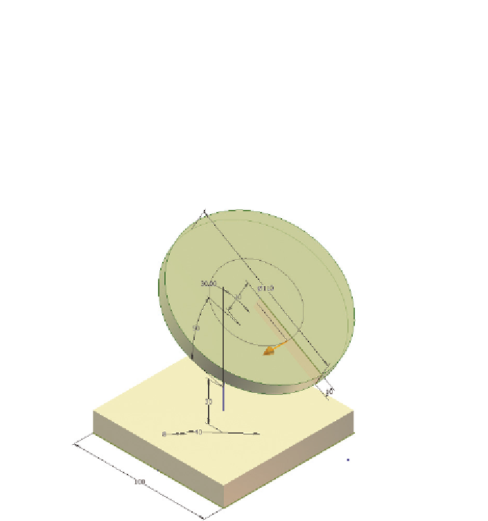
Select the centerline that is in line with the 30 mm dimension.
This will immediately produce a preview of the new feature
(Figure 3.21). Note that an arrow allowing for the changing of the
angle is available.
6.
Finish the Revolve tool by clicking the green check mark.
FIGURE 3.21
A preview of the Revolve tool
Now you can complete the main features of the part.
Creating Sweep Features
In this exercise, you'll create two features. The first will establish the outer por-
tion and will be hollow. The second will cut through the top and bottom plates.
1.
Make certain that the 2013 Essentials project file is active, and then
open
c03-10.ipt
from the
Parts\Chapter3
folder.
2.
Start the Sweep tool from the Create panel on the 3D Model tab.
Adding the circles to Sketch1 has made it a multiloop sketch, so
there is more than one option; the button for profile selection in the
dialog box will have a red arrow. This means Inventor needs you to
make a selection.

Search WWH ::

Custom Search