Graphics Programs Reference
In-Depth Information
Reusing Sketch Geometry
On a complex part where there are many features created from the same base
plane, you can sometimes use a single sketch to define more than one feature.
Certification
Objective
1.
Continue using the drawing from the previous exercise or make
certain that the 2013 Essentials project file is active, and then open
c03-06.ipt
from the
Parts\Chapter3
folder.
2.
Click the small + icon in the browser next to Extrusion1. This exposes
the sketch that was consumed by that feature.
3.
Right-click the sketch, and select Share Sketch from the context menu.
The sketch now appears both under and above the extrusion fea-
ture. It also becomes visible in the Design window so other features
can use it. In this case, you need to add to it first.
4.
Click the top face of the extrusion. When you do, icons will appear for
Edit Extrude, Edit Sketch, and Create Sketch.
5.
Click Edit Sketch.
6.
The Center Point Circle tool is on the marking menu and in the Draw
panel. Start it, and draw a circle based on the part center point with a
diameter of 40.
Your sketch might
rotate so that you're
looking directly at
it. To create images
in an isometric view,
I have disabled this
feature in the appli-
cation options to
show that sketches
can be edited in this
way, as well.
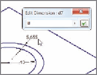
7.
Draw a larger circle using the same center with no diameter dimen-
sion; then, press the Esc key to stop the Circle tool. See Figure 3.16.
8.
Start the Dimension tool, and click the two circles. This will create a
dimension showing the distance between the perimeters. Set it to 8,
and finish the Dimension tool.
9.
Finish editing the sketch.


Search WWH ::

Custom Search