Information Technology Reference
In-Depth Information
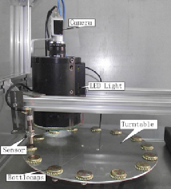
Fig. 4.
Device for capturing image
320
300 pixels. Due to the monochrome images can satisfy the precision of
the testing needs, we use monochrome camera in the experiment. We present
the assessment on the performance of the proposed method in comparison to
other similar techniques. The three main results are obtained and described
below, which are rotating alignment accuracy, run time and defect detection
effectiveness.
Firstly, the proposed CRPH solution in this paper is compared to the orien-
tation code method (OCM) [6], the morphological component analysis (MCA)
solution [7] in order to verify the rotation matching result. Fig.5 demonstrates
the rotating alignment result using three methods above between the template
image and the sample image. In OCM rotation alignment experiment, 64 orien-
tation codes are used, that corresponding to a sector width
Δ
θ
of
π
/32 radians.
We pre-built the OCM histogram set of the template image as the comparison
reference, which play similar role as the sparse dictionary of our method. The
motivation of creating orientation code histogram set is to reduce the time for
matching, as well as to have the same environmental conditions to compare with
the other two methods equivalently. A circular region with empirical radius of
36 pixels is used as the OCM base element, which is extracted orientation code
histogram as a base atom of the OCM histogram set. The center of the OCM
base circular region is bounded in a small field which is tolerance range for the
printing deviation of caps surface image. In the case, a circular region with ra-
dius 3 pixels is used tolerance field of the image deviation. Thus, the pixels of
the tolerance field are served as the center of the OCM base element. In other
words, each pixel corresponds to a OCM base element. Orientation code his-
tograms extracted from these base elements are put into the OCM histogram
set. The searching and rotation alignment methods adopt the methods of litera-
ture [6]. The result is shown in Fig.5(c). In our propose method, the projection
of the templates on 360 orientations (namely interval angle
Δθ
=1
o
) are created
×


Search WWH ::

Custom Search