Information Technology Reference
In-Depth Information
Fig. 5.
The actual manufacture of linear generator
Fig. 6.
The vertical view of linear generator
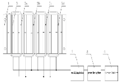
In Figure 4,1represents the iron yoke which is a part of the speed control hump. The
motor is connected to the middle part of speed control hump. 2 is coils, namely the
stator fixed in the bottom panel. 3 is the permanent magnet, and the arrows represent
the relative direction of motion of the magnetic field line direction. The motor rotor
and the stator are connected by a spring. The motor rotor and the stator can move
vertically rather than horizontally.
2.3
Rectifier Unit and Pressure Limiting Device
Because the speed control hump is a linear reciprocating generator, the system
generates alternating current. The bridge rectifier device turns direct current into
alternating current. Changing into the direct current, this current restores the battery to
a charged condition.

Search WWH ::

Custom Search