Information Technology Reference
In-Depth Information
named 1stOpt15PRO, a T-G-P model could be expressed by a function:
P
=
f
(
T,G
).
In this work, the fitting function is:
P
=(
c
1+
c
2
∗
G
+
c
3
∗
G
(
2)+
c
4
∗
T
)
/
(1+
c
5
T
). In which c1=-0.1754, c2=0.1132, c3=4.0779E-5, c4=0.0032, c5=0.000235.
After measuring the value of temperature and light intensity, the MPP in that
condition could be calculate through this function. In addition, the PV output
voltage at MPP can be regarded as constant in every sampling time.
∗
T−G−P
200
150
100
50
0
40
30
1200
1000
20
800
600
10
400
0
200
Temperature
Radiation Intensity
Fig. 3.
The effects of T and G on MPP
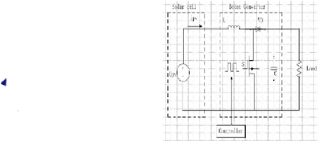
Fig. 4.
Photovoltaic system
3 Modeling of Photovoltaic Energy Converter
Photovoltaic system consists of solar power, DC-DC converter, and controller.
Fig.4 shows the photovoltaic system implemented in this work. Power switch S
could realize MPPT control by changing duty cycle.
The main control objective in this paper is to drive the switch with a duty
cycle to make the PV output current equals to its reference. Two equations of
are built when the switch is on and off. For output current and converter output
voltage should be controlled,
i
and
v
o
are selected as state variables. The sampling
period is set the same with PWM period T
s
, the system switches between the
following two subsystems:
When S is on:
x
=
A
1
x
+
B
1
u
y
=
Cx
kT
s
≤
T<kT
s
+
t
on
(2)
When S is off:
x
=
A
2
x
+
B
2
u
y
=
Cx
kT
s
+
t
on
≤
T<
(
k
+1)
T
s
(3)


Search WWH ::

Custom Search