Information Technology Reference
In-Depth Information
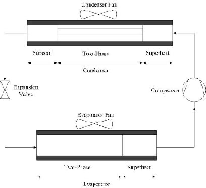
Fig. 1.
Vapor compression refrigeration cycle. The system has four components: a
compressor, a condenser, an expansion valve, and an evaporator.
where ˙
m
k
is the mass flow rate of the refrigerant through the compressor,
ω
k
is the motor shaft speed,
V
k
is the effective displacement volume of the
compressor,
C
k
and
D
k
are volumetric eciency coecients for the compressor,
n
is the polytropic coecient,
P
ki
and
P
ko
are the inlet pressure and outlet
pressure across the compressor, respectively.
2) Condenser: According to the state of refrigerant, the condenser can be
divided into three sections: a subcooled liquid section, a two-phase section and
a superheated vapor section. The condenser model has 7 states and 5 inputs. It
can be expressed by a non-linear state space form shown below:
Z
c
(
x
c
,u
c
)
·
x
c
=
f
c
(
x
c
,u
c
)
(2)
where the state variables are: length of the two condensation regions
L
c
1
and
L
c
2
;
refrigerant pressure
P
c
; refrigerant outlet enthalpy
h
co
; the wall temperatures in
the three regions
T
cw
1
,
T
cw
2
,and
T
cw
3
, respectively, the input variables are mass
flow rate of the inlet and outlet, ˙
m
ci
and ˙
m
co
; refrigerant inlet enthalpy
h
ci
;air
temperature
T
ca
and air mass flow rate ˙
m
ca
; respectively.
3) Expansion valve: The expansion valve is also modeled as a static compo-
nent; its mass flow rate can be calculated from the orifice equation
P
vo
)]
n
˙
m
v
=
C
v
A
v
[
ρ
v
(
P
vi
−
(3)
where ˙
m
v
is the mass flow rate of refrigerant through expansion valve,
C
v
is the
orifice coecient,
A
v
is the opening area,
ρ
v
is the refrigerant density.
P
vi
and
P
vo
are the inlet and outlet pressure across the expansion valve, respectively.
4) Evaporator: Similar to the condenser model, the evaporator can be di-
vided into two regions, i.e., a two-phase region with a mean void fraction, and a
Search WWH ::

Custom Search