Information Technology Reference
In-Depth Information
4 Design of Boundary Feedback Control
The boundary feedback control for a single canal and cascaded canal networks
can be designed according to the following unified procedure
Step 1: Determine the function relationship between
A
1
(0
,t
)and
H
1
(0
,t
),
and also the relationship between
A
i
(
L,t
)and
H
i
(
L,t
), (
i
=1
,
2) according
to the trapezoidal cross section, and substituting these relationships into (18).
Particularly when
n
= 1, it is the case of a single canal.
Step 2: Select the parameters
m
i
,(
i
=0
,
1
,
2) such that
ρ
(abs(
∇
g
(
0
)))
<
1.
Particularly when
n
= 1, select
m
0
and
m
1
such that
|
m
0
m
1
|
<
1, which is just
the case of a single canal.
Step 3: Substitute the expressions achieved by Step 1 and Step 2 into the gate
discharge relationships to obtain the boundary feedback control laws.
5 Application Examples
This section will show how to derive the boundary conditions according to the
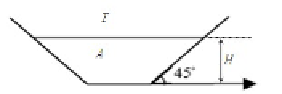
procedure. A canal with a trapezoidal cross section, as depicted in Fig. 3, is
selected as an example to demonstrate the advantages of the proposed boundary
feedback control.
Fig. 3.
Schematic of a canal with a constant trapezoidal cross section
Under this type of cross section, we use the boundary conditions of (10) to
compute the boundary conditions as follows
⎧
⎨
2
A
√
A
+1
H
(0
,t
)(
H
(0
,t
)+2)
A
V
(0
,t
)=
V
1+
m
0
1
−m
0
g
−
−
2
A
√
A
+1
H
(
L,t
)(
H
(
L,t
)+2)
A
,
|
m
0
m
1
|
<
1
.
V
(
L,t
)=
V
+
1+
m
1
1
−m
1
g
⎩
−
(19)
For the canal delimited by two underflow gates shown in Fig. 1, the gate discharge
relationships are expressed by
x
=0:
A
2
(0
,t
)
V
2
(0
,t
)=2
gu
0
(
H
up
−
H
(
A
(0
,t
)))
,
x
=
L
:
A
2
(
L,t
)
V
2
(
L,t
)=2
gu
L
(
H
(
A
(
L,t
))
(20)
−
H
do
)
,
where
u
0
and
u
L
are respectively the gate opening heights.
H
(
A
(0
,t
)) and
H
(
A
(
L,t
)) are the upstream and downstream water heights inside the canal.
H
up
and
H
ab
are the water heights outside the canal.


Search WWH ::

Custom Search