Information Technology Reference
In-Depth Information
Fig. 3.
The membership functions
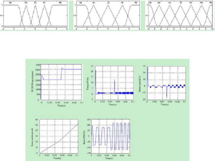
Fig. 4.
Simulation results of command speed mutation
could be concluded that IMC-fed BLDCM system can track the command speed
signal. Figure 4(b) is the torque waveform of BLDCM. When BLDCM operates
at steady stage, the torque is about 1Nm. Figure 4(c) shows the 120 electrical
degrees of stator current. Figure 4(d) is the rotor position. When BLDCM was
accelerated, the rotor position changed faster. Figure 4(e) is the back EMF.To
verify speed servo performance further, suppose the command speed is a liner
slope signal. It declined from 2000r/min at 0s to 0r/min at 0.2s. Figure 5 illus-
trated that IMC-fed BLDCM speed servo system could track command speed at
any time with good performance. Suppose the command speed wais 2000r/min
all the time. The load torque was 1Nm at 0s and changed to 3Nm at 0.05s. The
simulation results are in Figure 6.Figure 6(a) shows that when given sudden
load torque, BLDCM still remained the command speed, while the load torque
changed from 1Nm to 3Nm, as is shown in Figure 6(b). At the same time, the
stator current became larger in order to provide larger power. Suppose the com-
mand position was 20rad at 0s and changed to 40rad at 0.2s.The simulation
results are in Figure 5. Figure 7 showed that IMC-fed BLDCM position servo
system could track the command position signal. When fuzzy P controller is em-
ployed in position loop, the performance is improved. IMC-fed BLDCM position
servo system with fuzzy P controller could track the command position faster
than that with traditional P controller. Before reach the command position,
Search WWH ::

Custom Search