Information Technology Reference
In-Depth Information
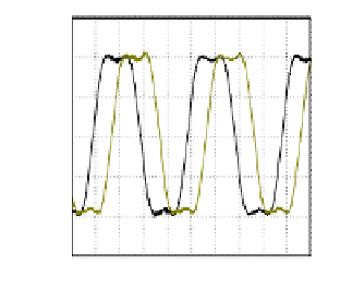
Fig. 6.
Switching signals of VSI in No.1 section
The algorithm raised in the paper is experimentally verified. In the exper-
iment, the PMSM parameters are:
Rs
=17
Ω
,
Ld
1=55
mH
,
Lq
1=81
mH
,
Ld
3=45
mH
,
Lq
3=32
mH
,
L
13=11
mH
,
J
=0
.
006
Kgm
2
,
P
=4.ThePWM
frequency is 10 kHz.
The current of phase A and B is shown in Fig.7 when
K
q
3
is zero in steady
state. The current of phase A and B when
K
q
3
=0
.
15 is shown in Fig.7 in steady
state.
Fig. 7.
Phase A and B when
K
q
3
is zero
Fig. 8.
Phase A and B when
K
q
3
isn't
zero
In Fig.7, the current only contains the fundamental component. In Fig.8, the
current also contains the three harmonic component, which can increase the
electromagnetic torque because of the three harmonic flux of the air gap. And
the amplitude of phase current doesn't need to increase in this condition.
The dynamic responses of electromagnetic torque are shown in Fig.9 and
Fig.10. The Fig.9 corresponds with
K
q
3
= 0, the fig.10 corresponds with
K
q
3
=
0
.
15. In these experiments, the current references
i
q
1
and
i
q
3
varies in step mode.
And the amplitude of phase current is as same as Fig.7 and Fig.8.


Search WWH ::

Custom Search