Information Technology Reference
In-Depth Information
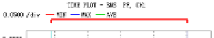
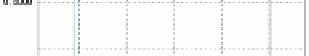
Fig. 3.
Power factor of 6.3KV bus
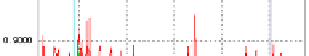
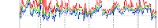
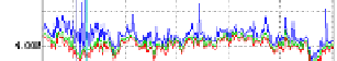
Fig.4.
Reactive power of 6.3KV bus
After all, it must not be overlooked that there are some over compensations and
shocks of power reactor that caused by high power device such as service incline
winch. Figure2 to Figure4 show that there are not only some distortions of harmonic
current but also shocks of power reactor which must be considered for improving
power supply quality of a Coal Mine.
Due to cost, efficiency,
power, and form factor constraints, a device that consists of
PPF, TSC and FC was put forward in this paper. By comparing figure3 to figure4 the
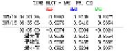
maximum capacity of PPF and remained FC can determined by following expression
+ = − =
(1)
There 6600kVar and 1200kVar is original compensation capacity and over
compensation capacity of secondary side of the transformer respectively. Considering
the compensation effect of original fixed capacitor the capacity of TSC can expressed
as follows
QQ
6600
1200
5400(kVar)
FC
PPF
=++=
(2)
The major difficulty is that how to avoid the resonance of PPF, TSC and FC occurs.
It needs to analyze all impossible combination between equivalent reactance of the
transformer, every channel of TSC, FC, and PPF under the harmonic current that
caused by harmonic loads. For this purpose, the thermodynamics modeling method
that consists of network topology and statistics was used to analyze impossible
resonance of proposed device.
Q
150
300
600
1050(kVar)
TS
C
3
Thermodynamics Modeling Method
The network topology [14-15] of equivalent inductance, TSC, FC and PPF is shown
in Figure5. Based on the capacity and the short-circuit impedance of the transformer
the equivalent inductance of 6.3kV power system can be calculated by following
expression
(
)
(3)
2
(
)
2
3
L u
=
/
S
=
9.06 /100
×
6300 / 2000
×
10
=
1.80(mH)
s
sec
ond
N


Search WWH ::

Custom Search