Environmental Engineering Reference
In-Depth Information
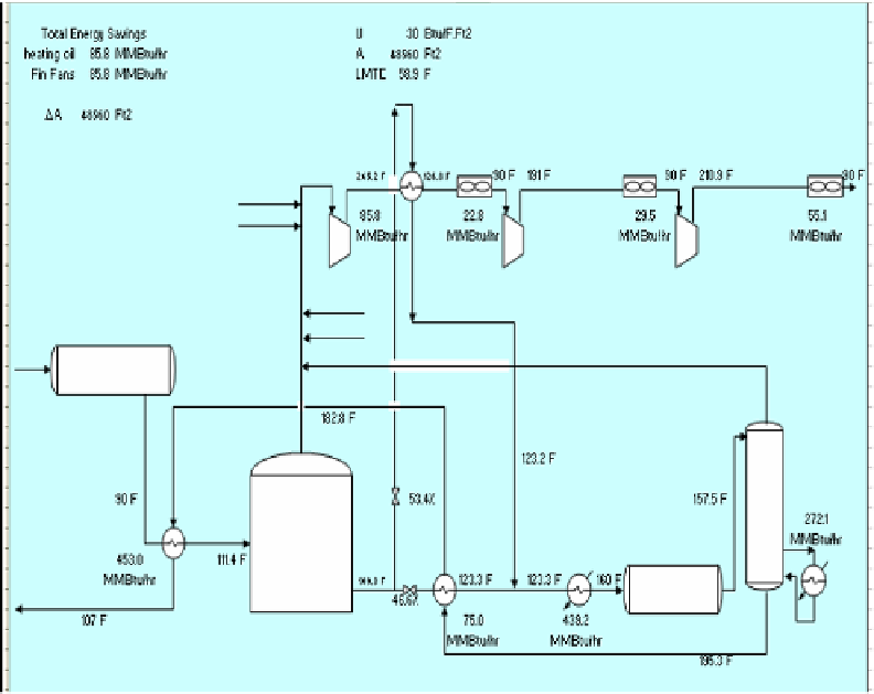
Figure 4. Oil and Gas Separation Design Option # 1
Pushing the envelope for more reduction in both energy consumption and GHG
emissions lead us to design option # 2 shown in figure 5 below. In this design option two heat
exchangers have been added to the base case design to integrate the discharge of the first and
third stage compressors with a branch from the crude stream before the desalter. Again the
relocation of the stabilizer bottoms feed heat exchanger has been also implemented and extra
duty for the reboiler has been added. In this design option more waste heat has been
recovered and consequently more GHG emissions have been reduced as follows; about 124
MM Btu/h savings in heating oil duty and about 260 T/d reductions in GHG emissions and
of-course again more savings in air cooling duties.
Further push towards more reduction in heating oil duty and GHG emissions through
design modification produces design options three, four and five shown in Figures 6, 7 and 8.
In these three new design options, three heat exchangers have been added to the base case
design but with different surface area requirements as shown in the three figures below.
The reduction in heating oil duties are 128.6 MM Btu/h, 139.4 MM Btu/h and 142.9 MM
Btu/h; respectively and the reduction in GHG emissions due to such reduction in heating oil
duties are 270 t/d, 292 t/d and 300 t/d; respectively too.
It is instructive to note here that the reduction in both heating oil duties and GHG
emissions with the increase in number of heat exchanger and associated surface area is
happening with steeper change. About 60 % of the reduction in GHG emissions can be
attained with 50 % of extra heat exchangers surface area.