Environmental Engineering Reference
In-Depth Information
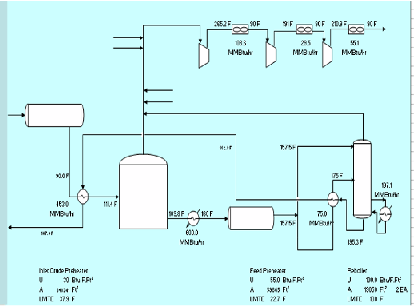
Figure 1. Typical Oil and Gas Separation Process Flow Diagram
The design shown above is used as a base case to make comparisons among other design
options regarding energy consumption, capital investment, expressed in terms of number of
heat exchangers and its surface area, and the GHG emissions reductions.
Heat integration role is not only to save energy consumption and its environmental
impact but also it can save some capital investment.
Table 1.
Stream
Name
TS
[F]
1
De-gassing Tank Feed
90.0
2
Desalter Feed
109.8
3
Stabilizer Feed
157.5
4
Stabilizer Btms to Reb
165.0
5
Stb Btm Product
195.3
6
Atm Comp 1st stg
265.2
7
HP Comp 1st stg
191.0
8
HP Comp 2nd stg
210.9