Environmental Engineering Reference
In-Depth Information
Fig. 3.29 Example of a parallel-rod wave guide for time domain reflectometry (TDR)
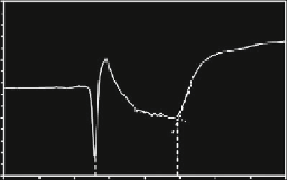
Fig. 3.30 Example of wave-
form data obtained by a TDR
device with a 0.2-m parallel-
rod wave guide (see
Fig.
3.29
) installed in a
mineral soil. Times
t
1
and
t
2
indicate the travel time of
signals reflected from the top
and bottom of the wave guide
3000
2500
2000
1500
t
1
t
2
1
2
3
4
5
travel time (ns)
For low-salinity soils, relative dielectric permittivity (
ε
r
) is given by
2
ε
r
¼ð
c
=
v
EM
Þ
(3.45)
Equation
3.45
only gives approximate values for soils with high electrical conductiv-
ity (Ferr
´
and Topp
2002
). Volumetric water content is estimated from a calibration
curve relating
ε
r
. For a large variety of agricultural mineral soils, a “universal”
formula of Topp et al. (
1980
) has been found to yield reasonably accurate values of
θ
v
and
θ
v
:
ε
r
2
10
6
ε
r
3
θ
v
¼
0
:
053
þ
0
:
0292
ε
r
0
:
00055
þ
4
:
3
(3.46)